DRV-28 inverter
s Troubleshooting
-249-
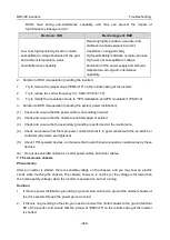
RCDs have strong anti-interference capability, and thus can prevent the impact of
high-frequency leakage current.
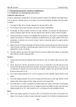
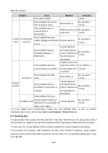
Electronic RCD
Electromagnetic RCD
Low cost, high sensitivity, small in volume,
susceptible to voltage fluctuation of the grid
and ambient temperature, weak
anti-interference capability
Requiring highly sensitive, accurate, and
stable zero-phase sequence current
transformer, using permalloy
high-permeability materials, complex process,
high cost, not susceptible to voltage
fluctuation of the power supply and ambient
temperature, strong anti- interference
capability
2.
Solution to RCD misoperation (handling the inverter)
1.
Try to remove the jumper cap at "EMC/J10" on the middle casing of the inverter.
2.
Try to reduce the carrier frequency to 1.5 kHz (P00.14=1.5).
3.
Try to modify the modulation mode to "3PH modulation and 2PH modulation" (P8.40=0).
3.
Solution to RCD misoperation (handling the system power distribution)
(1)
Check and ensure that the power cable is not soaking in water.
(2)
Check and ensure that the cables are not damaged or spliced.
(3)
Check and ensure that no secondary grounding is performed on the neutral wire.
(4)
Check and ensure that the main power cable terminal is in good contact with the air switch or
contactor (all screws are tightened).
(5)
Check 1PH powered devices, and ensure that no earth lines are used as neutral wires by these
devices.
(6)
Do not use shielded cables as inverter power cables and motor cables.
7.7.5 Live device chassis
Phenomenon
After an inverter is started, there is sensible voltage on the chassis, and you may feel an electric
shock when touching the chassis. The chassis, however, is not live (or the voltage is far lower than
the human safety voltage) when the inverter is powered on but not running.
Solution
1.
If there is power distribution grounding or ground stud on the site, ground the cabinet chassis of
the drive system through the power ground or stud.
2.
If there is no grounding on the site, you need to connect the motor chassis to the ground terminal
PE of the inverter, and ensure that the jumper at "EMC/J10" on the middle casing of the inverter
is shorted.

