DRV-28 inverter
s Function parameter list
-207-
Function
code
Name
Detailed parameter description
Default
value
Modi
fy
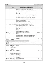
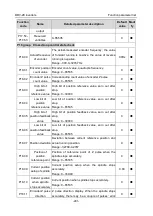
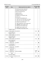
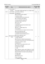
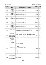
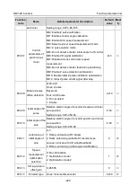
Bit4: Z pulse capture mode
Bit5: Do not detect encoder initial angle in v/f control
Bit6: Enable CD signal calibration
Bit7: Disable sin/cos sub-division speed
measurement
Bit8: Do not detect encoder fault during autotuning
Bit9: Enable Z pulse detection optimization
Bit10: Enable initial Z pulse calibration optimization
Bit12: Clear Z pulse arrival signal after stop
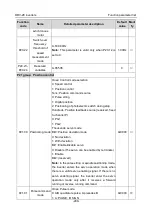
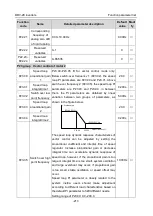
P20.08
Enable Z pulse
offline detection
0x00–0x11
Ones: Z pulse
0: Do not detect
1: Enable
Tens: UVW pulse (for synchronous motor)
0: Do not detect
1: Enable
0x10
○
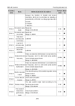
P20.09
Initial angle of Z
pulse
Relative electric angle of encoder Z pulse and motor
pole position.
Setting range: 0.00–359.99
0.00
○
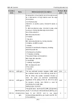
P20.10
Initial angle of the
pole
Relative electric angle of encoder position and motor
pole position.
Setting range: 0.00–359.99
0.00
○
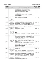
P20.11
Autotuning of
initial angle of
pole
0–3
1: Rotary autotuning (DC brake)
2: Static autotuning (suitable for resolver-type
encoder, sin/cos with CD signal feedback)
3: Rotary autotuning (initial angle identification)
0
◎
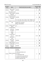
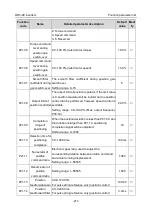
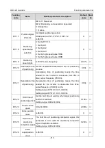
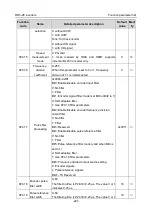
P20.12
Speed
measurement
optimization
selection
0: No optimization
1: Optimization mode 1
2: Optimization mode 2
1
◎
P20.13
CD signal zero
offset gain
0–65535
0
○
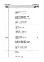
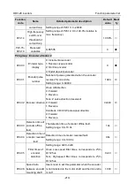
P20.14
Encoder type
selection
Ones: Incremental encoder
0: without UVW
1: with UVW
Tens: Sin/Cos encoder
0: without CD signal
1: with CD signal
0x00
◎


