DRV-28 inverter
s Extension cards
-307-
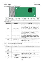
LED
Color
State
Description
LED1
Green
3.3V power indicator
LED2
(Bus state indicator)
Red
On
No network connection
Blinking
The connection to the network cable
between the Profinet controller is OK,
but the communication is not
established.
Off
Communication with the Profinet
controller has been established
LED3
(System fault indicator)
Green
On
Profinet diagnosis exists
Off
No Profinet diagnosis
LED4
(Slave ready indicator)
Green
On
TPS-1 protocol stack has started
Blinking
TPS-1 waits for MCU initialization
Off
TPS-1 protocol stack does not start
LED5
(Maintenance state
indicator)
Green
Manufacturer-specific - depending on
the characteristics of the device
LED6/7
(Network port state
indicator)
Green
On
PROFINET communication card and
PC/PLC have been connected via a
network cable
Off
PROFINET communication card and
PC/PLC have not been connected yet
LED8/9
(Network port
communication
indicator)
Green
Blinking
PROFINET communication card and
PC/PLC are communicating
Off
PROFINET communication card and
PC/PLC are not yet communicating
Electrical connection:
The Profinet communication card adopts a standard RJ45 interface, which can be used in a linear
network topology and a star network topology. The linear network topology electrical connection
diagram is shown below.
Master
device
Slave device 2
RJ45
RJ45
Slave device 1
RJ45
RJ45
Slave device n
RJ45
RJ45
Linear network topology electrical connection diagram
Note: For the star network topology, users need to prepare Profinet switches.
The star network topology electrical connection diagram is shown below:


