DRV-28 inverter
s Function parameter list
-223-
Function
code
Name
Detailed parameter description
Default
value
Modi
fy
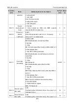
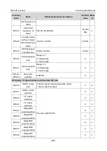
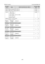
BIT2: S7 virtual terminal
BIT3: S8 virtual terminal
BIT4: S9 virtual terminal
BIT5: S10 virtual terminal
BIT6: HDI3 virtual terminal
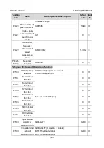
P25.10
HDI3 terminal
switch-on delay
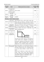
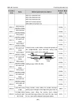
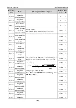
These function codes define corresponding delay of
the programmable input terminals during level
variation from switch-on to switch-off .
Si electrical level
Si valid
invalid
invalid
Switcn-on
delay
Switcn-off
delay
valid
Setting range: 0.000–50.000s
0.000s
○
P25.11
HDI3 terminal
switch-off delay
0.000s
○
P25.12
S5 terminal
switch-on delay
0.000s
○
P25.13
S5 switch-off
delay
0.000s
○
P25.14
S6 terminal
switch-on delay
0.000s
○
P25.15
S6 switch-off
delay
0.000s
○
P25.16
S7 terminal
switch-on delay
0.000s
○
P25.17
S7 switch-off
delay
0.000s
○
P25.18
S8 terminal
switch-on delay
0.000s
○
P25.19
S8 switch-off
delay
0.000s
○
P25.20
S9 terminal
switch-on delay
0.000s
○
P25.21
S9 switch-off
delay
0.000s
○
P25.22
S10 terminal
switch-on delay
0.000s
○
P25.23
S10 switch-off
delay
0.000s
○
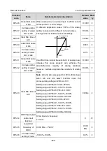
P25.24
Lower limit value
of AI3
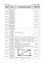
These function codes define the relation between
analog input voltage and corresponding set value of
analog input. When the analog input voltage
exceeds the range of max./min. input, the max. input
or min. input will be adopted during calculation.
0.00V
○
P25.25
Corresponding
setting of lower
limit of AI3
0.0%
○

