DRV-28 inverter
s Communication protocol
-265-
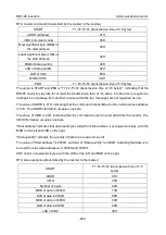
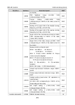
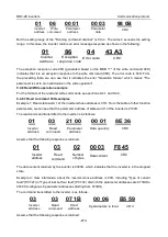
LSB of to-be-written data
88H
LSB of CRC
C5H
MSB of CRC
6EH
END
T1-T2-T3-T4 (transmission time of 3.5 bytes)
Note:
The sections 9.2 and 9.3 mainly describes the command formats. For the detailed application,
see the examples in section 9.4.8.
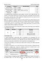
9.4.3 Command code: 08H, diagnosis
Sub-function code description
Sub-function code
Description
0000
Return data based on query requests
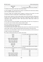
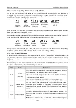
For example, to query about the circuit detection information about the inverter whose address is 01H,
the query and return strings are the same, and the format is described in the following tables.
RTU master command
START
T1-T2-T3-T4 (transmission time of 3.5 bytes)
ADDR
01H
CMD
08H
MSB of the sub-function code
00H
LSB of the sub-function code
00H
MSB of data
12H
LSB of data
ABH
LSB of CRC CHK
ADH
MSB of CRC CHK
14H
END
T1-T2-T3-T4 (transmission time of 3.5 bytes)
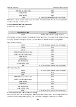
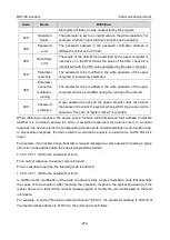
RTU slave response
START
T1-T2-T3-T4 (transmission time of 3.5 bytes)
ADDR
01H
CMD
08H
MSB of the sub-function code
00H
LSB of the sub-function code
00H
MSB of data
12H
LSB of data
ABH
LSB of CRC CHK
ADH
MSB of CRC CHK
14H
END
T1-T2-T3-T4 (transmission time of 3.5 bytes)
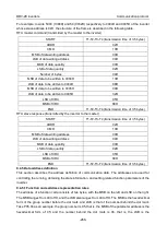
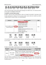
9.4.4 Command code: 10H, continuous writing
The command code 10H is used by the master to write data to the inverter. The quantity of data to be
written is determined by "Data quantity", and a maximum of 16 pieces of data can be written.

