


16.9.3.1
Design
GUID-B643C994-D0BA-4BE9-BACB-ADEA0197CAE4 v1
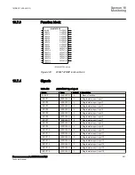
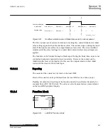
illustrates the general logic diagram of the function.
BLOCK
CountType
INPUT
RESET
ERROR
OVERFLOW
LIMIT1 … 4
CounterLimit1...4
MaxValue
OnMaxValue
InitialValue
VALUE
Operation
Counter
Overflow
Detection
Limit
Check
Error
Detection
IEC12000625_1_en.vsd
IEC12000625 V1 EN-US
Figure 231:
Logic diagram
The counter can be initialized to count from a settable non-zero value after reset of the
function. The function has also a maximum counted value check. The three
possibilities after reaching the maximum counted value are:
•
Stops counting and activates a steady overflow indication for the next count
•
Rolls over to zero and activates a steady overflow indication for the next count
•
Rolls over to zero and activates a pulsed overflow indication for the next count
The pulsed overflow output lasts up to the first count after rolling over to zero, as
illustrated in figure
.
Section 16
1MRK 511 408-UUS A
Monitoring
586
Phasor measurement unit RES670 2.2 ANSI
Technical manual
Содержание Relion RES670
Страница 1: ...RELION 670 SERIES Phasor measurement unit RES670 Version 2 2 ANSI Technical manual ...
Страница 2: ......
Страница 276: ...270 ...
Страница 306: ...300 ...
Страница 360: ...354 ...
Страница 406: ...400 ...
Страница 614: ...608 ...
Страница 732: ...726 ...
Страница 748: ...742 ...
Страница 884: ...878 ...
Страница 932: ...926 ...
Страница 933: ...927 ...


