


22.8.2
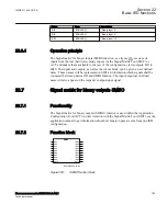
Function block
SEMOD54866-4 v3
SMMI
^AI1
^AI2
^AI3
^AI4
^AI5
^AI6
^AI1
^AI2
^AI3
^AI4
^AI5
^AI6
IEC05000440.vsd
IEC05000440 V3 EN-US
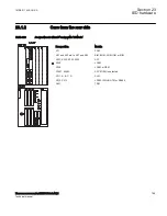
Figure 300:
SMMI function block
22.8.3
Signals
SEMOD55924-1 v2
PID-3832-INPUTSIGNALS v5
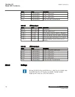
Table 607:
SMMI Input signals
Name
Type
Default
Description
AI1
REAL
0
SMT connected milliampere input
AI2
REAL
0
SMT connected milliampere input
AI3
REAL
0
SMT connected milliampere input
AI4
REAL
0
SMT connected milliampere input
AI5
REAL
0
SMT connected milliampere input
AI6
REAL
0
SMT connected milliampere input
PID-3832-OUTPUTSIGNALS v5
Table 608:
SMMI Output signals
Name
Type
Description
AI1
REAL
Analog milliampere input 1
AI2
REAL
Analog milliampere input 2
AI3
REAL
Analog milliampere input 3
AI4
REAL
Analog milliampere input 4
AI5
REAL
Analog milliampere input 5
AI6
REAL
Analog milliampere input 6
22.8.4
Operation principle
SEMOD55908-4 v6
The Signal matrix for mA inputs (SMMI) function, see figure
, receives its inputs
from the real (hardware) mA inputs (the MIM boards) via the Signal Matrix Tool
(SMT), and makes them available to the rest of the configuration via its analog outputs,
named AI1 to AI6. The inputs, outputs, as well as the whole block, can be given user-
defined names which will be represented in SMT and ACT.
1MRK 511 408-UUS A
Section 22
Basic IED functions
Phasor measurement unit RES670 2.2 ANSI
785
Technical manual
Содержание Relion RES670
Страница 1: ...RELION 670 SERIES Phasor measurement unit RES670 Version 2 2 ANSI Technical manual ...
Страница 2: ......
Страница 276: ...270 ...
Страница 306: ...300 ...
Страница 360: ...354 ...
Страница 406: ...400 ...
Страница 614: ...608 ...
Страница 732: ...726 ...
Страница 748: ...742 ...
Страница 884: ...878 ...
Страница 932: ...926 ...
Страница 933: ...927 ...


