


7.1.6.5
Operating and inhibit conditions
M13877-38 v4
Figure
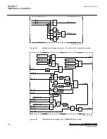
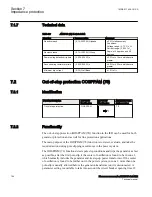
presents a simplified logic diagram for the Power swing detection function
ZMRPSB (68). The internal signals DET1of3 and DET2of3 relate to the detailed logic
diagrams in figure
respectively.
Selection of the operating mode is possible by the proper configuration of the
functional input signals REL1PH, BLK1PH, REL2PH, and BLK2PH.
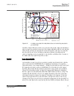
The load encroachment characteristic can be switched off by setting the parameter
OperationLdCh
=
Disabled
, but notice that the
D
Fw and
D
Rv will still be calculated
from
RLdOutFw
and
RLdOutRv
. The characteristic will in this case be only
quadrilateral.
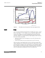
There are four different ways to form the internal INHIBIT signal:
•
Logical 1 on functional input BLOCK inhibits the output PICKUP signal
instantaneously.
•
The INHIBIT internal signal is activated, if the power swing has been detected and
the measured impedance remains within its operate characteristic for the time,
which is longer than the time delay set on
tR2
timer. It is possible to disable this
condition by connecting the logical 1 signal to the BLK_SS functional input.
•
The INHIBIT internal signal is activated after the time delay, set on
tR1
timer, if
an ground-fault appears during the power swing (input IOCHECK is high) and the
power swing has been detected before the ground-fault (activation of the signal
I0CHECK). It is possible to disable this condition by connecting the logical 1
signal to the BLK_I0 functional input.
•
The INHIBIT logical signals becomes logical 1, if the functional input I0CHECK
appears within the time delay, set on
tGF
timer and the impedance has been seen
within the outer characteristic of ZMRPSB (68) operate characteristic in all three
phases. This function prevents the operation of ZMRPSB (68) function in cases,
when the circuit breaker closes onto persistent single-pole fault after single-pole
autoreclosing dead time, if the initial single-pole fault and single-pole opening of
the circuit breaker causes the power swing in the remaining two phases.
1MRK 511 408-UUS A
Section 7
Impedance protection
Phasor measurement unit RES670 2.2 ANSI
153
Technical manual
Содержание Relion RES670
Страница 1: ...RELION 670 SERIES Phasor measurement unit RES670 Version 2 2 ANSI Technical manual ...
Страница 2: ......
Страница 276: ...270 ...
Страница 306: ...300 ...
Страница 360: ...354 ...
Страница 406: ...400 ...
Страница 614: ...608 ...
Страница 732: ...726 ...
Страница 748: ...742 ...
Страница 884: ...878 ...
Страница 932: ...926 ...
Страница 933: ...927 ...


