Specialized Concentrated Focused
「
36
」
Menu Functions
In terms of position, lead-in/out line can also be divided into inner lead-in/out line and outer lead-in/out
line, which depends on which part is to be reserved after machining.
If a selected object is under [Fill] mode, the system will set it as outer lead-in/out; if a selected object is
under [Unfill] mode, the system will set it as inner lead-in/out.
[Set Intersecting Line]
This option is to cut any shape on a circular tube. To cut a shape on a circular tube, the cylinder with
this shape as the intersecting surface and the circular tube should be intersected, so cutting trajectory
should be intersecting line of the two solids. The system gives cutting trajectory with the help of this
item, so there is no need for the user to draw the intersecting line in the tool path.
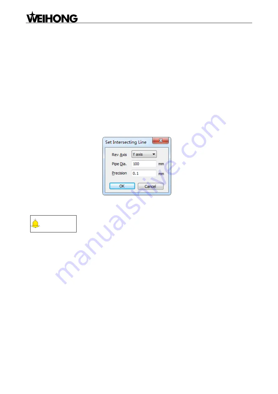
After this option is selected, a dialog will pop up, as shown in Fig. 4-23.
Fig. 4-23 Set intersecting line
Diameter of steel tube and cut precision can be set in the above dialog.
CAUTION
Diameter of steel tube must be larger than maximum height of selected shape.
[Set Kerf Compensation (Ctrl + R)]
Kerf compensation is the amount of cutting path offset required to compensate for the material
removed by the plasma cutting process. In unilateral cutting, the offset between dimensions of actually
processed workpiece and theoretically processed workpiece is half of the kerf width; in bilateral cutting,
the offset is the kerf width. With no kerf compensation, outer outline of actually processed workpiece
becomes smaller while inner outline becomes bigger. The method of kerf compensation in our system
is as follows:
1) Select an object to be compensated;
2) Select
―Set Kerf Compensation‖ under ―Object‖ menu or under right-click menu to eject a dialog as
shown in Fig. 4-24.


