Specialized Concentrated Focused
Advantageous Functions
「
77
」
2) Directly setting compensation on the interface. Enter position, positive measured value and
negative measured value in the interface as shown in Fig. 6-3, positive error, reverse error and
reverse clearance calculated automatically. Then save the data file under the corresponding
configuration folder. In this way, automatic compensation will be performed during machining
according to the value in the file.
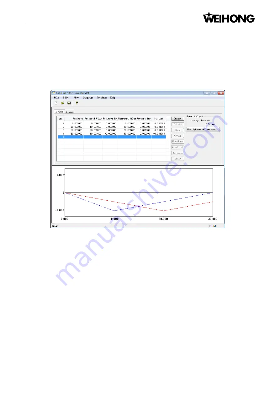
A visualized path graph, as shown in Fig. 6-4, will be generated according to the input data.
Fig. 6-4 Lead screw error compensation generation interface
In the above picture, the red line indicates the path of positive motion; the blue line the path of reverse
motion; the middle gray line the ideal path.
Currently, this tool can save the lead screw error compensation file as two versions: V9 and V12,
which can be switched under [Settings] menu.
V9 version supports X, Y and Z axes while V12 version, its interface as shown in Fig. 6-3, supports X
and Y axes.
6.1.3. Effect of Lead Screw Error Compensation
Composed of unidirectional error correction, traditional compensation adds backlash compensation
simultaneously in reverse motion to improve moving precision. Although this kind of compensation can
improve the control precision of a semi-closed machine tool to some extent, the precision after
compensation of a point which is located precisely before compensation can not be ensured according
to experiments.


