A3: Axis Monitoring, Protection Zones
2.2 Axis monitoring
Basic Functions
Function Manual, 09/2011, 6FC5397-0BP40-2BA0
95
2.2.6
Limit switches-monitoring
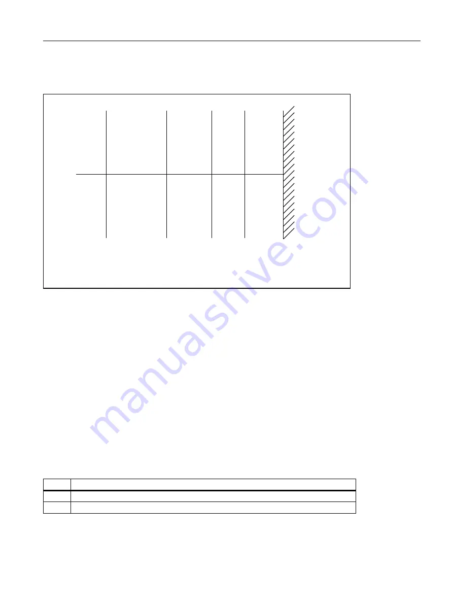
Overview of the end stops and possible limit switch monitoring:
2.2.6.1
Hardware limit switches
Function
A hardware limit switch is normally installed at the end of the traversing range of a machine axis. It serves to
protect against accidental overtravelling of the maximum traversing range of the machine axis while the machine
axis is not yet referenced.
If the hardware limit switch is triggered, the PLC user program created by the machine manufacturer sets the
corresponding interface signal:
DB 31, ... DBX12.0 / 12.1 = 1 (Hardware limit switch minus / plus)
Parameterization
The braking behavior of the machine axis upon reaching the hardware limit switch is configurable via the
machine data:
MD36600 $MA_BRAKE_MODE_CHOICE (Braking behavior on hardware limit switch)
Value
Significance
0
Braking with the configured axial acceleration
1
Rapid stop (set velocity = 0)
QGVRIWZDUH
OLPLWVZLWFK
DFWLYDEOHYLD
3/&
VWVRIWZDUH
OLPLWVZLWFK
0HFKDQLFDO
WUDYHUVLQJOLPLW
+DUGZDUHOLPLW
VZLWFK
(0(5*(1&<
6723


