Specifications and External Dimensions
ZW User's Manual
283
APPENDICES
10
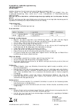
External Dimensions
●
ZW-S07/S20/S30/S40
●
ZW-SR07/SR20/SR40
64
16
4
(Unit: mm)
4-
φ
3.5
(Mounting holes)
43
16
Measurement
center
M
(
N
ote1)
M
(
N
ote1)
Lighting and
receiving axis
(40)
Standard fiber cable (
φ
2.0)
Connector
16
±0.1
16
±0.1
4
±0.1
43
±
0.1
Standard surface
Mounting hole dimensions
4-M3
24
24
12
Caution
label
Measurement
CE
N
TER
X (
N
ote1)
L
(
N
ote1)
Measurement end
FAR
Measurement end
N
EAR
(
φ
10)
(42)
(50)
Standard
surface
Standard
surface
Standard
surface
N
ote 1.
Type
L
M
ZW-S07
7
0.3
ZW-S30
30
3
X
12
ZW-S20
20
1
11.8
11.7
ZW-S40
40
6
11.7
(Unit: mm)
Note 1.
Type
L
M
ZW-SR07
7
0.3
ZW-SR40
ZW-SR20
20
1
40
6
12
32.5
24
(23.6)
(24)
24
24
12
(40)
64
8.5
(50)
23.6
12
(24)
4-M3
Standard
surface
(23.6)
(24)
(12)
(24)
(64)
4±0.1
16±0.1
16±0.1
43±0.1
43
16
Mounting hole dimensions
16
4
(42)
Standard
surface
4-
φ
3.5
(Mounting holes)
Standard fiber
cable (
φ
2.0)
Lighting and
receiving axis
M
(Note1)
M
(Note1)
L
(Note1)
Measurement end
FAR
Measurement end
NEAR
Measurement
CENTER
Standard
surface
Caution
label
Connector
(
φ
10)
Measurement
CENTER
Summary of Contents for ZW-C1*T
Page 70: ...Operating with Sensor Controller 68 ZW User s Manual MEMO ...
Page 116: ...Setting the System 114 ZW User s Manual MEMO ...
Page 134: ...Controll input signal with PC tool 132 ZW User s Manual MEMO ...
Page 209: ...8 Troubleshooting Troubleshooting 8 1 Error Messages 208 8 2 Troubleshooting 210 ...
Page 319: ...Index ZW User s Manual 317 Index 11 ...
Page 321: ......