


325
F3SG-SR
User’s Manual
Chapter
6
Wiring Exa
m
p
le
s
(f
or F3
SG-SR)
Input/Output Circuit and Applications
E
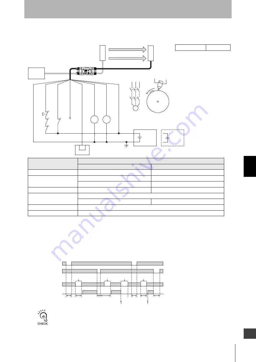
6-2-1-10. Single Break with EDM and Intelligent Tap
[Wiring Example]
• When using the Intelligent Tap (F39-SGIT-IL3) with the emitter and receiver connected, the following functions are not available.
- External Test
- Operating Range Selection by wiring
- Optical Synchronization
• When a functional earth is necessary, wire an earth cable according to the example in
Optical Synchronization and EDM Unused
. Also refer to
5-4-4. Functional Earth Connection
for more information.
S1
KM1
S2
KM2
F39-SGIT
24 VDC
IO-Link
Master *3
Wiring for NPN *1
24 VDC
F39-JG
□
B-L/
XS5F-D521-DJ0-IL
F39-JG
A-D
F39-JGR3K-L
F39-JGR3K-D
IN
PLC *2
24V/0V (Brown)
Not used (Pink)
PSDI (Gray)
0V/24V (Blue)
OPERATING RANGE
SELECT INPUT (Yellow)
AUX (Red)
OSSD 1 (Black)
OSSD 2 (White)
*4
KM1
KM2
KM1
KM2
M
Cam
S2
Receiver
Emitter
: Indicates a switch position
Function
Setting
DIP switch *6
SD Manager 3
EDM
-
[External device monitoring] : Enable
Operating Range Selection *5
-
[Operating Range Selection] : Long mode
-
[Operating Range Selection] : Short mode
PSDI
N/A
[PSDI] : Single break
Non-Muting system
Perform wiring according to the wiring diagram.
N/A
[Muting] : Disable
External Test not used
N/A
Wired Synchronization
Connect the emitter and receiver with the Intelligent Tap.
*1. Reverse the polarity of the power supply when using in the NPN system. Select a
PLC of PNP or NPN type according to the system of your application.
*2. When connecting to the PLC, the output mode must be changed with the SD
Manager 3 according to your application. Refer to
Manager 3
for more information on setting the functions by the SD Manager 3.
*3. For connecting with the IO-Link Master unit, refer to an instruction manual of the IO-
Link Master unit you use.
*4. This is the case for a PELV circuit.
*5. It is possible to set either Long or Short mode.
*6. The PSDI is only configurable by the SD Manager 3, not by the DIP Switch.
S1: Reset switch
S2: Press position switch
KM1, KM2: Safety relay with forcibly guided contacts
(G7SA) or magnetic contactor
PLC: Programmable logic controller (Used for monitoring
only. NOT related to safety system.)
M: Motor
Timing chart
Reset switch (S1)
Press position switch (S2)
OSSD
T1: Minimum pressing time of reset switch.
Configurable from 100 to 500 ms in 100-ms
increments by SD Manager 3.
T2: Minimum break time (300 ms)
T3: Minimum pressing time of press position
switch. T3 = T1
T4: Wait time until single break is complete (30 s
or less)
* When the machine is stopped by unintended
block in the middle of pressing of parts, operation
of the switch (S1) and then a single dummy break
are needed for reinitiation of the machine cycle.
T1 min. T2 min.
Feeding
parts
T3 min.
T3 min.
T2 min.
T1 min.
T4
Machine stops
Machine restarts
Feeding
parts
Unintended
block
Dummy
break *
Unblocked
Blocked
Intelligent Tap
Needed
Summary of Contents for F3SG-SR Series
Page 1: ...Safety Light Curtain F3SG SR Series User s Manual Man No Z405I E3 01...
Page 18: ...xvi Introduction F3SG SR User s Manual...
Page 156: ...128 Chapter 2 IO Link F3SG SR User s Manual System Operation and Functions...
Page 340: ...312 Chapter 5 Cascade Connection F3SG SR User s Manual Wiring and Installation...
Page 368: ...340 Chapter 7 Maintenance Checklists F3SG SR User s Manual Checklists...
Page 398: ...370 Chapter 8 Revision History F3SG SR User s Manual Appendix...


