background image

120Eg User Guide - Upgrading Your System

4 - 29

12. 

Close the front cover, plug in the system power cord(s), and turn on the system.

Swapping a Hard Disk Drive

When you are swapping out a faulty hard drive, you can determine which drive to
remove by checking its SCSI drive activity/fault LED..  

Note:


When the SCSI drive activity/fault LED indicates a

drive fault (steady amber light), you can remove the drive and
swap in a replacement at any time without needing to power
down the system and provided RAID is configured in the
system. Drive manufacturer's caution against moving a drive
that is still spinning because of possible damage to the drive.
Also, when the SCSI or S-ATA drive activity/fault LED indicates
that the hard disk drive is being rebuilt (flashing amber light) do
not remove the drive.

1. 

Observe the safety and ESD precautions listed under 

General Information

 and

Static Precautions

 at the beginning of this chapter.

2. 

Open the front door of your system's cabinet. 

3. 

Remove the drive and its carrier from the SCSI or S-ATA hard disk drive bay

by performing the following procedures:

Caution

Depending on the drive fault, the drive may be still spinning
when you remove it. Follow the next steps exactly when
removing drives.

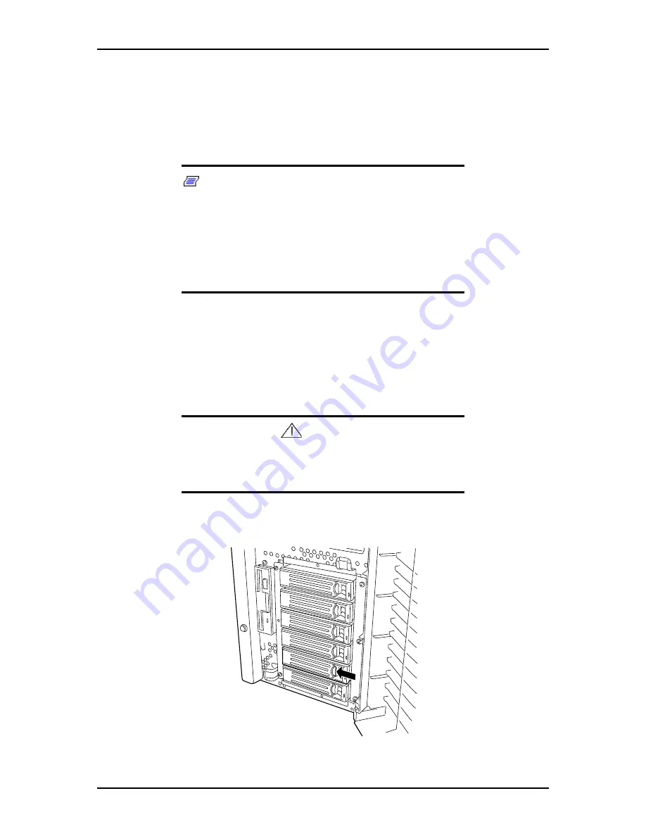
Press the disk carrier handle lock inward to release it. See "Figure 4 - 23:
Releasing the Disk Carrier Tray" on page 4-29.

Figure 4 - 23: Releasing the Disk Carrier Tray

Summary of Contents for Express 5800 120Eg

Page 1: ... User s Guide Express 5800 120Eg ...

Page 2: ......

Page 3: ... suitability of specific product configurations and applications must be determined by the customer and is not warranted by NEC Computers International To allow for design and specification improvements the information in this document is subject to change at any time without notice Reproduction of this document or portions thereof with out prior written approval of NEC Computers International is ...

Page 4: ......

Page 5: ...ont View Door Opened 1 7 Chassis Rear View 1 10 Internal View 1 13 Motherboard 1 14 Standard Features 1 16 System Functions 1 17 Power Supply 1 17 Peripheral Bays 1 17 Disk Array 1 18 Automatic Rebuilding Function 1 19 Expand Capacity Function 1 19 Remote Power On Feature Wake On LAN 1 21 AC LINK Feature 1 21 Security 1 21 Security with Mechanical Locks and Monitoring 1 21 Software Locks via the B...

Page 6: ...2 23 POST Execution Flow 2 23 POST Error Messages 2 25 Power Off 2 25 SLEEP Switch 2 25 Configuring Your System 3 1 Configuring Your System 3 2 BIOS Setup Utility 3 3 Using the BIOS Setup Utility 3 3 BIOS Setup Configuration Settings 3 4 Main Menu 3 5 Advanced Menu 3 6 Processor Summary Submenu 3 6 Advanced Chipset Control Submenu 3 7 IDE Configuration Submenu 3 7 Floppy Configuration Submenu 3 8 ...

Page 7: ... 5 Removing or Installing the Processor Air Duct 4 6 Removing the Processor Air Duct 4 6 Installing the Processor Air Duct 4 7 Installing or Removing 5 25 inch Devices 4 8 Installing a 5 25 Inch Media Device 4 9 Removing a 5 25 Inch Media Device 4 12 Installing or Removing Hard Disk Drives 4 14 Installing or Swapping a Hard Disk Drive in a Non Hot Swap Disk Drive Bay 4 15 Installing a Hard Disk Dr...

Page 8: ...g SCSI RAID Drive Configuration 4 64 Power Cable 4 65 Hot plug SCSI RAID Drive Configuration 4 66 Problem Solving 5 1 Problem Solving 5 2 Static Precautions 5 2 Resetting the Server 5 3 Forced Shutdown 5 4 Maintenance 5 5 Making Backup Copies 5 5 Cleaning 5 5 Cleaning the Server 5 6 Cleaning the Interior 5 6 Cleaning CD ROM 5 8 System Diagnostics 5 10 Test Items 5 10 Starting and Ending the System...

Page 9: ...Cannot turn the power OFF at the blue screen 5 26 The server is not found on the network 5 26 Problems with NEC EXPRESSBUILDER 5 27 Problems with Express Setup 5 28 Following message appeared when you tried to install Express Setup to the hard disk that has smaller capacity than the specified partition size 5 28 The message can not be displayed correctly when copying the files from CD ROM or check...

Page 10: ...5 34 Preparing for Memory Dumping 5 34 Saving the Dump File 5 35 Recovery for Windows 2000 System 5 36 Off line Maintenance Utility 5 38 Starting the Off line Maintenance Utility 5 38 Features of Off line Maintenance Utility 5 39 If You Need Assistance 5 40 Error Messages 5 41 Error Messages after Power on 5 41 POST Error Messages 5 41 Beep Codes 5 45 How to Identify BIOS Revision Level 5 46 Statu...

Page 11: ...ork Driver D 12 Optional Network Board Driver D 13 Installation of the Optional Network Board Driver D 14 Installing SCSI Controller Driver D 14 Setting for Solving Problems D 15 Memory Dump Debug Information D 15 Windows Dr Watson D 16 Network Monitor D 17 Installing Maintenance Utilities D 18 Updating the System D 18 Making Backup Copies of System Information D 18 Exceptional Setup D 18 Installa...

Page 12: ...LDER E 3 DOS Based ExpressBuilder Menus E 4 Starting Windows Based ExpressBuilder E 8 Windows Based ExpressBuilder Menus E 9 Online Document E 9 Setup E 9 Quit E 10 Appendix F F 1 Configuration Diskette Creator F 1 Creating Configuration Diskette F 1 Appendix G G 1 Installing and Using Utilities G 1 NEC ESMPRO G 1 Functions and Features G 1 Installing ESMPRO G 2 Promise Array Management G 2 Power ...

Page 13: ...4 8 Figure 4 6 Removing the Dummy Cover 4 9 Figure 4 7 Attaching the Device Mounting Rails 4 10 Figure 4 8 Securing a Removable Media Device 4 11 Figure 4 9 SCSI Interface Cable 4 12 Figure 4 10 Hard Disk Drive Installation Scheme 4 15 Figure 4 11 Releasing the Disk Carrier Tray 4 17 Figure 4 12 Removing the Disk Carrier Tray 4 17 Figure 4 13 Placing the Hard Drive into a Disk Carrier Tray 4 18 Fi...

Page 14: ... Floppy Disk Drive 4 55 Figure 4 45 Connectors on the back of a CD DVD ROM or CD RW drive example 4 56 Figure 4 46 Jumper settings example 4 56 Figure 4 47 Connectors on the Back of a Tape Drive example 4 57 Figure 4 48 Standard Configuration Connections 4 60 Figure 4 49 S ATA RAID Drive Configuration Connections 4 61 Figure 4 50 SCSI Hard Disk Drive Configuration Connections 4 62 Figure 4 51 SCSI...

Page 15: ...le 3 14 Security Menu 3 11 Table 3 15 Server Menu 3 13 Table 3 16 System Management Submenu 3 14 Table 3 17 Console Redirection Submenu 3 14 Table 3 18 Event Log Configuration Submenu 3 15 Table 3 19 Boot Menu 3 16 Table 3 20 Boot Settings Configuration Submenu 3 16 Table 3 21 Exit Menu 3 18 Table 3 22 RAID Creation Methods 3 23 Table 4 1 Functions of a Disk Array Controller 4 47 Table 4 2 IDE Dev...

Page 16: ...120Eg User Guide Table of Contents xiv ...

Page 17: ...vides details about the EXPRESSBUILDER CD ROM It also provides rack version of your system specific information Chapter 2 helps you installing the server in an appropriate place make connec tions and start using your system Chapter 3 shows you how to configure your system and helps you set up the vari ous options Chapter 4 provides all the information you need to remove components from your system...

Page 18: ...jury or loss of life Caution Cautions indicate situations that can damage the system hard ware or software Note Notes give important information about the material being described Names of keyboard keys are printed as they appear on the keyboard For example Ctrl Alt or Enter Text or keystrokes that you enter appear as boldface type For example type abc123 and press ENTER File names are printed in ...

Page 19: ...ncluded with your system either as electronic files on the EXPRESSBUILDER CD ROM or as paper copy shipped with your server System Release Notes Release Notes provide you with the latest information about your system This information was not available to be included in your user s guide at the time it was developed and released ...

Page 20: ...et Before doing the procedures in this manual make sure that your system is powered off and unplug the AC power cord from the back of the chassis Failure to disconnect power before opening your system can result in personal injury and equipment damage In the U S A and Canada the power cord must be a UL listed detachable power cord in Canada CSA certified type ST or SJT 16 AWG 3 conductor provided ...

Page 21: ...cuits to the external ports Remote Earths To prevent electrical shock connect all local individual office computers and computer support equipment to the same electrical circuit of the building wiring If you are unsure check the building wiring to avoid remote earth conditions Earth Bonding For safe operation only connect the equipment to a building sup ply that is in accordance with current wirin...

Page 22: ...Let the system warm or cool to room temperature before using it Keep the system away from magnetic forces Keep the system dry Do not wash the system with a wet cloth or pour fluid into it Protect the system from being bumped or dropped Check the system for condensation If condensation exists allow it to evaporate before powering on the system Keep the system away from dust sand and dirt ...

Page 23: ...ystem Features on page 1 3 Chassis Front View on page 1 6 Chassis Rear View on page 1 10 Internal View on page 1 13 Motherboard on page 1 14 Standard Features on page 1 16 Optional Features on page 1 23 EXPRESSBUILDER CD ROM on page 1 24 100 ...

Page 24: ...embly Figure 1 1 Tower based System Your server may include a non redundant non hot swap power supply or redundant hot swap power supply module containing up to two power supply units Your server may also include a non hot swap SCSI or S ATA hard disk drive cage or a hot swap SCSI or S ATA hard disk drive cage The non hot swap SCSI or S ATA hard disk drive cage supports four 1 0 inch hard disk dri...

Page 25: ... chassis Four removable media expansion bays High degree of hard disk drive fault tolerance and advanced disk array management features through the use of RAID Technology if the optional RAID controller is installed or using the embedded S ATA host RAID controller Embedded PC compatible support serial mouse keyboard diskette USB LAN and video Integrated onboard ATI RAGE XL Video Graphics Array VGA...

Page 26: ...ptional RAID controller is installed or using the embedded S ATA host RAID controller Embedded PC compatible support serial mouse keyboard diskette USB LAN and video Integrated onboard ATI RAGE XL Video Graphics Array VGA controller with 8 MB of video memory Optional SCSI or S ATA controller Refer to specifications in the guide accompanying the controller board Integrated onboard Network Interface...

Page 27: ...ay management features through the use of RAID technology if an optional RAID controller is installed SCSI backplane is Ultra 320 ready Hot Swap S ATA Hard Disk Drive Bays Four hot swap 1 0 inch S ATA hard disk drive bays accessible from the front of the chassis that allows 3 5 inch S ATA hard disk drives to be swapped in or out of the system without powering it down if RAID is configured in the s...

Page 28: ...lock the front door 3 Stabilizers 4 Use the stabilizers to prevent the server from falling down 4 LAN ACCESS lamp green See the section lamp Indicator Description later in this chapter 5 DISK ACCESS lamp green See the section lamp Indicator Description later in this chapter 6 POWER SLEEP lamp green Lights in green when the server is powered on Flashing green indicates that the system is in ACPI sl...

Page 29: ...120Eg User Guide System Overview 1 7 Front View Door Opened Figure 1 3 Front View Non Hot Swap Hard Disk SCSI or IDE Bay Figure 1 4 Front View Hot Swap Hard Disk SCSI Drive Bay 1 2 1 2 ...

Page 30: ...serted CD ROM 2 1 Headphone jack 2 2 Volume control 2 3 Access lamp lights amber to indicate drive activity 2 4 CD ROM slot 2 5 Emergency eject hole 2 6 Open Close button 3 Hard disk drive bay Depending on your configuration your server may be equipped with a 6 or a 4 hard disk drive bay 4 3 5 inch floppy disk drive Insert a 3 5 inch floppy disk into the 3 5 inch floppy disk drive to read data fro...

Page 31: ...section lamp Indicator Description later in this chapter 8 Reset button To reset the system press the reset button momentarily To clear CMOS press and hold the reset button for at least four seconds then press the power button Release both the reset and power buttons at the same time The system will power on and the CMOS will be reset 9 Dump switch NMI switch Causes a non maskable interrupt The du...

Page 32: ...120Eg User Guide System Overview 1 10 Chassis Rear View Figure 1 7 Rear View Non Redundant System 1 2 3 4 5 6 7 8 9 10 11 12 13 ...

Page 33: ...mp goes on green when the power of the server is turned on 1 4 Power status lamp The lamp goes amber if the power is defected 1 5 Additional power supply slot An optional power supply may be installed on the slot 2 AC inlet The AC inlet is connected with the power cord 3 Serial port B connector The serial port B connector is used to connect the server to a device with the serial interface The serv...

Page 34: ...h keyboard coming with the server 8 Monitor connector The monitor connector is connected with the display unit 9 Serial port A connector The serial port A connector is connected with a device having the serial interface 10 Maintenance LEDs and switches 11 Link ACT lamp The Link ACT lamp shows the LAN access status 12 LAN connector The LAN connector is connected with a network system on LAN 1000BAS...

Page 35: ...ive is installed in slot 2 The device bay can include a maximum of two single height device and one double height device 5 3 5 inch floppy disk drive 6 Hard disk drive bay Hard disk drive bay can be equipped with four or six hard disk drives depending on the kind of drives that are installed S ATA SCSI hot swap non hot swap 7 Mother board 8 Rear cooling fan 1 2 3 4 4 4 3 4 2 4 1 5 6 7 8 ...

Page 36: ... and 2A arranged from left to right 4 CPU1 socket 5 CPU2 socket 6 Floppy disk drive connector 7 Ultra ATA66 connector for CD ROM drive 8 1 Front cooling fan connector 8 2 Redundant front cooling fan connector 9 Front panel interface connector 10 Serial ATA connectors for built in hard disk drives 11 Speaker 1 2 3 1 4 2 5 2 2 6 7 8 1 8 2 9 2 10 11 2 12 13 14 15 16 17 18 19 ...

Page 37: ...Serial COM B connector 15 LED connector 16 PCI board slots slots PCI 1 PCI 2 PCI 3 PCI 4 and PCI 5 arranged from bottom to top PCI 5 32 bit 33MHz PCI PCI 4 Not used in this system PCI 3 32 bit 33MHz PCI PCI 2 and 1 64 bit 66MHz PCI X 17 Lithium battery 18 Rear cooling fan connector 19 External connector ...

Page 38: ... Memory monitoring feature single bit error correction double bit error detection CPU memory degradation feature logical isolation of a failed device Temperature detection Error notification Internal fan monitoring feature Internal voltage monitoring feature BIOS password feature Security feature security lock Disk array option Hot Swap S ATA or SCSI HDD optional Redundant hot swap power supply op...

Page 39: ...ithout powering down the system Peripheral Bays The system supports a variety of standard PC AT compatible peripheral devices The chassis includes these peripheral bays A 3 5 inch front panel bay for installing the standard 3 5 inch floppy disk drive supports 720KB and 1 44MB floppy disk media Three 5 25 inch device bays for installing half height or full height 5 25 inch peripheral devices such a...

Page 40: ...t can also enhance the drive by improving the reliability and supporting an automatic rebuilding function All RAID levels are common in their basic operation due the fact that several hard disks can be recognized as one disk drive However performance cost and use are conditions that vary according to the RAID level You should select an appropriate configuration that is suitable for your system Fea...

Page 41: ...uilding function Do not turn the power off If power is turned off automatic rebuilding will not start Use an interval of 60 seconds or more between mounting and dismounting the hard disk drive If a hard disk is being rebuilt do not replace the hard disk Expand Capacity Function Disk capacity can be expanded by adding a disk drive while the system is running This function is only supported if the s...

Page 42: ...e network and perform other network jobs Sleep mode requires an operating system that supports its function ACPI The Advanced Configuration and Power Interface ACPI aware operating system can place the system into a state where the hard drives spin down some system fans stop and all processing is halted However in this state the power supply is still on and the processors are still dissipating som...

Page 43: ...r blackout etc Note The standard default value of the remote power on function is Disabled To enable it the Wake On LAN item in the Advanced menu of the BIOS Setup Utility described in Chapter 3 BIOS Setup Configuration Settings must be changed to Enabled AC LINK Feature When the power cord of the server is connected to an uninterruptible power supply UPS unit the server supports the power linkage...

Page 44: ...eo prevent keyboard or mouse input and to prevent use of the front panel reset sleep and power switches Disable writing to the diskette drive when secure mode is set Degradation Feature If a CPU or a memory DIMM error was detected during execution of POST Power On Self Test after system power is turned on the reconfiguration function isolates the failed CPU or memory DIMM and continues operation Y...

Page 45: ...g the standard 3 5 inch floppy disk drive in a converter supports 720KB and 1 44MB floppy disk media and optional file devices One slim CD ROM drive S ATA Configuration The hard disk drive bays for installing up to four S ATA hard disk drives SCSI Configuration With optional SCSI controller or RAID controller installed you can install up to four fix SCSI hard disk drives or up to three hot swap SC...

Page 46: ...diskettes third party software drivers Do Windows 2000 or Windows Server 2003 Hard Disk Installation using Express Setup See Appendix F on page F 1 Software End User License Agreement Carefully read the terms and conditions of the Software End User License Agreement printed on the EXPRESSBUILDER CD ROM sleeve ...

Page 47: ...page 2 2 Selecting a Site on page 2 3 Unpacking the System on page 2 5 Setting Up Your Server on page 2 6 Making Connections on page 2 8 Connecting Power Cord on page 2 10 Powering On Your System on page 2 21 Using the System on page 2 13 ...

Page 48: ...e System 2 Overview This chapter describes how to select a site unpack the system make cable connections and power on the system units Information on front and rear panel features switches and LEDs are also included in this chapter ...

Page 49: ...stem the power plug of both power supplies must be plugged in the same com mon ground power outlets Clean dust free and well ventilated Every side ventilating openings kept free of obstructions Away from sources of heat vibration or physical shock Isolated from strong electromagnetic fields and electrical noise produced by electrical devices such as air conditioners large fans large electric motor...

Page 50: ...120Eg User Guide Setting Up the System 4 Not doing so may result in overheating and damaging the system Easily accessible for system maintenance and installation of system upgrades ...

Page 51: ...ntainers prior to unpacking If the shipping boxes are damaged note the damage and if possible photograph it for reference After removing the contents of the containers keep the cartons and the pack ing materials If the contents appear damaged when you unpack the boxes file a dam age claim with the carrier immediately ...

Page 52: ... devices connected 6 Install an operating system to the server See Installing the Operating System with Express Setup on page D 1 7 Install the utilities in the provided NEC EXPRESSBUILDER CD ROM See Installing and Using Utilities on page G 1 8 After all the system setup procedures are completed make backup copies of system information System information is required for recovering the server from ...

Page 53: ...or to lift the server The front door may be disengaged and damage the server Do not install the server in the following locations as it may cause malfunctions of the server Places with drastic changes in temperature e g near a heater air conditioner or refrigerator Places with strong vibration Places with corrosive gas in presence near chemicals or with possibilities of chemicals sprayed over On a...

Page 54: ...ny damaged cable connector Do not use any unauthorized interface cable Do not use the server with any loose interface connection Do not step on the interface cable or place any heavy object on it Caution Power off the server and a peripheral device before connec tion Connecting a powered peripheral device to the pow ered server will cause malfunctions and failures To connect a third party peripher...

Page 55: ...l adapter B PS 2 Keyboard C Monitor D Network hub multiport repeater E Serial device e g modem Direct connection to a private telephone line is prohibited F PS 2 Mouse G Power cord to appropriate power source H Serial device e g modem Direct connection to a private telephone line is prohibited A B C D E F G H ...

Page 56: ... the server safely Fail ure to follow these instructions may cause a fire personal injury or property damage See Safety Notices on page 1 xviii for details Do not plug the power cord in to an improper power source Do not connect the power cord to an outlet that has an illegal number of connections Insert the power plug into the outlet as far as it goes Use the authorized power cord only 1 Plug the...

Page 57: ...ntrol unit such as an UPS unit confirm that the power control unit is powered OFF Connecting the power cord while power is supplied to the power control unit may cause a failure Warning A power cord is provided for each power supply shipped with your system Do not attempt to modify or use the supplied AC power cord if it is not the exact type required To connect the power cord from the server to a...

Page 58: ...er cord from the server is connected to a UPS change the BIOS setup of the server to link with power supply from the UPS Change parameter Resume AC Power Loss under the Server menu of the BIOS SETUP utility See Configuring Your System on page 3 1 for details ...

Page 59: ...g the floppy disk Turning off the server or ejecting the floppy disk while the access lamp is lit may damage data being stored on the floppy disk After turning off the server wait at least 10 seconds before turning it on again Cycling the power immediately may cause malfunction or failures of the server Before relocating the server turn off the power and unplug the power cord from the outlet Movin...

Page 60: ...ed security key Insert the provided security key into the key hole and turn the key to unlock the front door Then hold the front door edges and gently pull the door away from the computer chassis When you close the front door lock the door with the key for security Caution Do not open the front door by hanging the handle at the upper left corner with your claws If the front door cannot be opened e...

Page 61: ... a CD ROM drive have a function to eject a tray or media using a software command Before issuing a soft ware command to eject a tray or media confirm that the front door is open If the command is executed while the front door is closed a tray or media may run into the front door resulting in an error or may cause the unit to fail ...

Page 62: ...ed floppy disk is inserted the message notifying that date read is not available and the message prompting formatting are displayed Refer to the manual that comes with the OS to format the floppy disk If the floppy disk contains a system powering on or restart ing the server with the floppy disk inserted boots the system from the floppy disk To eject the floppy disk from the floppy disk drive pres...

Page 63: ... switch that prevents the stored data from accidental erasure You can read data from a write protected floppy disk but you cannot save data into the floppy disk or format it We recommend that you should write protect any floppy disk containing valuable data unless you are about to save data To write protect a 3 5 inch floppy disk use the write protect switch provided on its back Figure 2 5 Diskett...

Page 64: ...ive may be installed at the factory Setting and Removing the CD ROM Make sure that the server is powered the POWER SLEEP lamp is lit before inserting a CD ROM into the CD ROM drive Press the Open Close button on the front of the CD ROM drive to eject the tray With the CD ROM label facing up place a CD ROM in the tray gently and securely Press the Open Close button or gently push on the tray front ...

Page 65: ... ROM retract the tray back in place When you fail to eject When you fail to eject the CD ROM tray with the Open Close button and take out the CD ROM from the server follow the procedure below 1 Press the POWER switch to power off the server The POWER SLEEP lamp goes off 2 Insert a metal pin of approximately 1 2 mm in diameter and 100 mm in length a straightened large paper clip will make a substit...

Page 66: ...is side with your hand Place the CD ROM with its printed side upward and gently put it on the tray Do not scratch the CD ROM or write anything directly on it with a pencil or ball point pen Keep the CD ROM away from cigarette smoke Do not leave the CD ROM in a high temperature place e g place exposed to direct sunlight or close to a heater When dust or fingerprints are attached on the CD ROM wipe ...

Page 67: ...oor tower based system only and press the push button power on off switch on the front panel Verify that the system power lamp is lit If it is not lit ensure the AC power cord is connected to a functional AC power source Figure 2 6 Power Switch and Lamp After a few seconds your system begins the internal Power On Self Tests POST POST automatically checks the system board CPU s memory keyboard mous...

Page 68: ...e D 1 Caution If the power cord is connected to a power control device such as a UPS Uninterruptible Power Supply make sure that the power control device is powered If the power cord is connected to the server an initial diagno sis of the hardware starts The POWER switch does not work while in diagnosis Wait for about 10 seconds then press the POWER switch Always allow POST to complete before powe...

Page 69: ...in POST POST Power On Self Test is the self diagnostic program stored in the system memory When you power on the server the system automatically runs POST to check the mother board ECC memory module CPU module keyboard and mouse POST also displays messages of the BIOS setup utility such as the start up message while in progress With the factory setup of the server the splash screen appears on the ...

Page 70: ...eck These messages appear to indicate that the system has detected the CPU keyboard and mouse 3 After a few seconds POST displays the following message prompting you to launch the BIOS setup utility SETUP stored in the system memory of the server This message appears at bottom left on the screen Launch the BIOS SETUP utility when you need to change the settings to meet the requirements for the ser...

Page 71: ...e display unit screen See POST Error Messages on page 5 41 Caution Take a note on the messages displayed before consulting with your sales agent Alarm messages are useful information for maintenance Power Off Follow the procedure below to power off the server If the power cord of the server is connected to a UPS refer to the manual that comes with the UPS or the manual for the application that con...

Page 72: ...s of the previous operations To resume the original state press the SLEEP switch again It may take a little time to resume the original state Note The operational level in the power saving mode depends on the OS in use Available for the Windows operating system If you press the power sleep switch for more the 3 seconds it will force the server power off Caution Do not change system configuration w...

Page 73: ...3 Configuring Your System Configuring Your System on page 3 2 BIOS Setup Utility on page 3 3 S ATA Host RAID Utility on page 3 19 Configuring Motherboard Jumpers on page 3 27 ...

Page 74: ...ters are configured using the BIOS Setup which is stored in the system FLASH memory If your system has been factory configured the BIOS Setup Utility does not need to be run unless you want to change the password or security features add certain types of option boards or devices or upgrade your system board This chapter also provides information on several system configuration parameters that are ...

Page 75: ...y a submenu position the cursor on a selection that has a submenu and press ENTER An arrow precedes selections with submenus Refer to the following table for information on the keys that you use with BIOS Setup These keys are also listed at the bottom of the Setup menu Table 3 1 BIOS Setup Menus Menu Use Main Use this menu for basic system configuration Advanced Use this menu for setting the Advan...

Page 76: ...OS Setup Configuration Settings The BIOS Setup Configuration tables show the default settings for the BIOS Setup Utility and provide a place for you to record any changes you make to these settings Recommended values are bold in the following tables ...

Page 77: ... Displays the BIOS version and build date Processor Display only Displays processor information For details see Processor Summary submenu in the Advanced menu System Memory Display only Displays the system memory size detected by the BIOS System Time HH MM SS Set the System Time System Date MM DD YYYY Set the System Date Language French German Spanish Italian English US Set the language for the BI...

Page 78: ...t submenu Preproduct Debug Select submenu Table 3 5 Processor Summary Submenu Feature Choices or Display Only Description Your Setting Manufacturer Display only Displays the processor manufacturer name Brand String Display only Displays the processor brand ID Frequency Display only Displays the processor speed FSB Speed Display only Displays the processor Front Side Bus FSB CPU1 CPU2 CPUID Display...

Page 79: ...s the onboard S ATA controller Configure S ATA as RAID Disabled Enabled Sets the S ATA function as an IDE controller or RAID controller S ATA Ports Definition A1 3rd M A A2 4th M A1 4th M A A2 3rd M Defines S ATA port to IDE channel A1 indicates the left side S ATA connection Mixed P ATA S ATA Select submenu Displays the Mixed P ATA S ATA submenu The Mixed P ATA S ATA submenu defines the priority ...

Page 80: ...k drive controller Table 3 9 Super I O Configuration Submenu Feature Choices or Display Only Description Your Setting Serial Port A Address Disabled 3F8 IRQ4 3E8 IRQ4 2E8 IRQ3 Disables or selects the I O port address and interrupt for serial port A Serial Port B Address Disabled 2F8 IRQ3 3E8 IRQ4 2E8 IRQ3 Disables or selects the I O port address and interrupt for serial port B Table 3 10 USB Confi...

Page 81: ...ables or disables the onboard Network Interface Controller NIC Onboard NIC 1 10 100 1000 ROM Disabled Enabled Enables or disables the option ROM scan for the onboard Network Interface Controller NIC Table 3 12 Memory Configuration Submenu Feature Choices or Display Only Description Your Setting DIMM 1A 1B 2A 2B Display only Normal Not installed Disabled Displays the current status of the memory ba...

Page 82: ... 8 9 10 11 12 Selects the jitter setting from 4 to 12 For B0 stepping MCH this value should be 4 PCI_EXP_2 Device PCI_EXP_3 Device Auto Comp 1 0 Mode For x8 device 1 0 compliance mode bit only needs to be set for the first device For x4 device just one logical device needs to be set 1 0 compliance mode bit Hardware Prefetcher Disabled Enabled This option should be enabled in order to enable or dis...

Page 83: ...rs Press Enter to display the user password entry screen With a user password only certain menus are accessible This option is available only if the Administrator Password is set User Access Level No Access View Only Limited Full Access No Access prevents user access to the SETUP utility View Only allows access to the SETUP utility but no parameters are changeable Limited allows only limited field...

Page 84: ...bled Enabled Specify whether the system boots in secure mode This option is enabled when User Password is set The keyboard will remain locked until a password is entered Front Panel Switch Inhibit Disabled Enabled Enables or disables the POWER switch If Enabled is selected power off with the POWER switch becomes unavailable after OS boot up Forced shut down also becomes unavailable Forced shut dow...

Page 85: ...tem installed in the hard disk drive The action taken on timeout is determined by the Fault Resilient Boot Timer policy option PXE OS Boot Timeout Disabled 5 10 15 20 25 30 35 40 45 50 55 60 minutes Selects time limit for booting an operating system using PXE boot The action taken on timeout is determined by the OS Watchdog Timer policy option OS Watchdog Timer Policy Always Reset Retry 3 Times Th...

Page 86: ...rial number of system View only Chassis Part Number e g 856 060350 001 Indicates the part number of chassis View only Chassis Serial Number e g 04 Indicates the serial number of chassis View only BIOS Version e g 4N34 Indicates BIOS version number View only BMC Device ID Indicates BMC Device ID View only BMC Firmware Revision Indicates BMC firmware revision View only BMC Device Revision Indicates ...

Page 87: ...m event log BIOS Event Logging Disabled Enabled Select Enabled to allow logging of BIOS events Critical Event Logging Disabled Enabled Select Enabled to allow logging of the critical system errors The critical system errors are fatal to system operations such as PERR SERR ECC ECC Event Logging Disabled Enabled Select Enabled to allow logging of ECC error events PCI Event Logging Disabled Enabled S...

Page 88: ...om the option CD DVD Drives Select submenu In the submenu specify the 1st drive from the option Table 3 20 Boot Settings Configuration Submenu Feature Choices or Display Only Description Your Setting Quick Boot Disabled Enabled This option allows BIOS to skip several tests during the POST sequence This will decrease the time required for booting the system Quiet Boot Disabled Enabled If enabled th...

Page 89: ... set in this menu on booting Finding the boot software the server starts the software The priority of the boot devices can be changed by using the and keys Move the cursor to the desired device with the or key and change the priority with the or key Caution To boot NEC EXPRESSBUILDER set the priority of the devices listed above ...

Page 90: ...xit after writing all modified Setup item values to NVRAM F10 key can be used for this operation Discard Changes and Exit Exit leaving NVRAM unmodified User is prompted if any of the setup fields were modified Esc key can be used for this operation Discard Changes Read previous values of all Setup items from NVRAM Load Setup Defaults Load default values for all SETUP items F5 key can be used for t...

Page 91: ...alling the Hard Disk Drives Install the two serial ATA hard disk drives to your server Refer to Installing or Removing Hard Disk Drives on page 4 14 for detail Note use hard disks of the same capacity and revolution Activating the SATA RAID Feature To run the Array Configuration Utility ACU run the BIOS setup utility and change the SATA RAID Enable option in the Advanced menu to Enable Refer to BI...

Page 92: ...ys Use the Manage Arrays option to view array properties and members and delete arrays The following sections describe these operations in greater detail Viewing Array Properties To view the properties of an existing array 1 At the BIOS prompt press Ctrl A 2 From the ACU menu Array Configuration Utility 3 From the main menu select Manage Arrays 4 From the List of Arrays dialog box select the array...

Page 93: ...render array unusable Do you want to delete the array Yes No RAID 1 only the following prompt is also displayed Deleting the partition will result in data loss Do you also want to delete the partition Yes No 6 Press Y to delete the array or partition or N to return to the previous menu 7 Press Esc to return to the previous menu Creating Arrays Before creating arrays make sure the disks for the arr...

Page 94: ...re assigned you cannot change the array properties using the ACU Instead use Adaptec Storage Manager Browser Edition See SATA HostRAID Adaptec Storage Manager Browser Edition User s Guide included in the NEC Express Builder s online documentation for details To assign properties to the new array 1 In the Array Properties menu select an array type and press Enter Note that only the available array ...

Page 95: ...tion If you do there is no way to restart and no way to recover the data that was on the source drive Table 3 22 RAID Creation Methods RAID level Create via When appropriate RAID0 No Init Creating a RAID0 on new drives RAID0 Migrate Creating a RAID0 from on new drive and one drive with data you wish to preserve RAID1 Build Any time you wish to create RAID1 but especially if you have data on one dr...

Page 96: ...ome data miscompares if you later run a consistency check This is normal and is not a cause for concern The ACU allows you to use drives of different sizes in a RAID1 During a build operation however only the smaller drive can be selected as the source or first drive When migrating from single volume to RAID0 migrating from a larger drive to a smaller drive is allowed However the destination drive...

Page 97: ... used in an array you may not be able to use the array again Do not initialize a disk that is part of a boot array To determine which disks are associated with a particular array see Viewing Array Properties on page 3 20 To initialize drives 1 Turn on your server and press Ctrl A when prompted to access the ACU 2 From the ACU menu Array Configuration Utility 3 Select Initialize Drives 4 Use the up...

Page 98: ...enu select Disk Utilities 3 Select the desired disk and press Enter You are offered the following options Format Disk Simulates a low level format of the hard drive by writing zeros to the entire disk Serial ATA drives are low level formatted at the factory and do not need to be low level formatted again Caution Formatting destroys all data on the drive Be sure to back up your data before performi...

Page 99: ... page 3 28 shows the location of system board jumpers and the factory default settings for the password CMOS configuration jumper With the SETUP utility you can set desired passwords to protect the data stored in the server against access from unauthorized users When you forget the passwords however you may want clear them The following describes how to clear these passwords You can also use the f...

Page 100: ...powered off and unplug the AC power cords from the back of the chassis Failure to disconnect power before moving the jumpers can result in personal injury and equipment damage Observe static precautions Use an antistatic wrist strap A Not used B CMOS jumper Normal factory setting C CMOS jumper Clear CMOS D Password jumper Normal factory setting E Password jumper Clear password A B C D E A A A ...

Page 101: ...e the server and press the POWER switch 5 Power off the server upon completion of POST 6 Restore the jumper switch setting and power on the server for reconfiguration Clearing and Changing the Passwords To clear the passwords 1 Power off the system and remove the left side panel as described in Removing or Installing the Side Cover on page 4 4 2 Check to ensure the system power cord s is removed f...

Page 102: ...actory default position left pane of Figure 3 1 CMOS and Password Jumpers on page 3 28 to the Clear CMOS position right pane of Figure 3 1 CMOS and Password Jumpers on page 3 28 4 Connect the power cord s power on the system and after POST completes power down the system and unplug the power cord s 5 Move the Clear Password jumper to its default position 6 Replace the left side panel connect the p...

Page 103: ... Installing or Removing 5 25 inch Devices on page 4 8 Installing or Removing Hard Disk Drives on page 4 14 Installing or Swapping a Hard Disk Drive in a Non Hot Swap Disk Drive Bay on page 4 15 Installing or Removing a Processor on page 4 32 Installing or Removing a DIMM on page 4 38 Installing or Removing a PCI Board on page 4 43 Installing or Removing a RAID Controller Board on page 4 47 Replaci...

Page 104: ...or proper cooling and airflow always replace the side access panels before powering on your system WARNING Avoid burns If the system has been running any installed processor and heat sink on the processor board s will be hot To avoid the possibility of a burn be careful when removing or installing components that are located near processors Contact your sales representative or dealer for a list of...

Page 105: ...Preparing Your System for Upgrade To prepare your system for installation or removal of system components perform the following procedure 1 Observe the safety and ESD precautions listed under General Information and Static Precautions at the beginning of this chapter 2 Shutdown the operating system OS 3 If necessary press the power on off switch on the front panel of the server see Powering On You...

Page 106: ...serve the following instructions to use the server safely Fail ure to follow these instructions may result in death or serious personal injury See Safety Notices on page 1 xviii for details Disconnect the power plug before working with the server 1 See the Preparing Your System for Upgrade on page 4 3 to prepare 2 Loosen the two screws A in Figure 4 1 Removing the Side Cover on page 4 4 3 Slide th...

Page 107: ...rocedure of the removal Make sure that the hooks C on the side cover are inserted into the frame D and holes B of the server securely Caution After one or more optional devices are installed or removed completely install the removed side cover securely Figure 4 2 Installing the Side Cover B Holes C Hooks D Frame B C D ...

Page 108: ...es cooling efficiency and can affect performance or cause damage due to overheating Removing the Processor Air Duct Follow these steps to remove the air duct 1 See Preparing Your System for Upgrade on page 4 3 to prepare 2 Remove the side cover see Removing or Installing the Side Cover on page 4 4 3 Hold the left side of the air duct and push the right end of the tab to release from the chassis 4 ...

Page 109: ...duct 1 Holding the internal cables clear place the air duct into the chassis 2 Adjust the air duct until the frame A of the right end of the duct is aligned with the hook B on the chassis Figure 4 4 Replacing the Processor Air Duct 3 Reinstall the side cover see Removing or Installing the Side Cover on page 4 4 A B ...

Page 110: ...ight devices or one half height device and one full height device Set the SCSI termination of the 5 25 inch device to OFF and the SCSI ID to a value which is not assigned to any other device Refer to the vendor documentation that comes with the device on how to set the values For half height device first install a device in slot 1 Then install another device in slot 2 For full height device instal...

Page 111: ...e installing a media device The dummy cover is released by removing the two screws holding it in place see Figure 4 6 Removing the Dummy Cover on page 4 9 Save the dummy cover and screws for future use Note When installing a full height device remove two dummy covers Figure 4 6 Removing the Dummy Cover 5 Remove the device from its protective wrapper and place it on an antistatic surface Record the...

Page 112: ...se damage to the device Note When installing a double height device use the DLT device rails that come with the server Figure 4 7 Attaching the Device Mounting Rails 8 Install the media device into the bay as follows Move any cables in the bay out of the way Align the rails on the media device with the support guides in the bay Slide the device into the bay until the slide rails are flush with the...

Page 113: ...ased on the CD ROM drive normally installed 10 Secure the device to the system with the screws removed in step 4 above Figure 4 8 Securing a Removable Media Device 11 Connect the SCSI or IDE interface cable see Figure 4 9 SCSI Interface Cable on page 4 12 to the device Caution Connector pin bending or incomplete connection may cause a malfunction to occur Provide the connection securely watching t...

Page 114: ... of the device you are removing 3 Remove the two screws securing the device to the removable media device bay See Figure 4 8 Securing a Removable Media Device on page 4 11 4 Slide the removable media device out of the device bay and set it down on an antistatic surface Caution Observe static precautions Use an antistatic wrist strap 5 Remove the screws securing the device mounting rails to the dev...

Page 115: ...described earlier in this chapter Otherwise continue with the next step 7 Install a dummy cover into the vacated bay see Figure 4 6 Removing the Dummy Cover on page 4 9 8 Reinstall the left hand side access panel on the system chassis See Removing or Installing the Side Cover on page 4 4 9 Plug in the system power cord s and turn on the system ...

Page 116: ... hard disk drive bay in your system In each example the internal hard disk drives are located in the SCSI disk drive bays Caution Do not use any hard disks not approved by the server manufacturer If an unapproved third party s hard disk is installed in the server not only the hard disk but also the server itself may be damaged Consult your service representative for purchasing hard disk Observe sa...

Page 117: ...ard disk drive contact your sales representative or dealer If installing new drives follow an installation scheme starting with the bottom most drive Fill the bays bottom to top 1 through 4 Figure 4 10 Hard Disk Drive Installation Scheme SATA hard disk drive Optional SATA controller or RAID controller is required Hard Disk Bay to Install First hard disk Disk bay 1 Second hard disk Disk bay 2 Third...

Page 118: ...etal surface on your system when handling parts Installing a Hard Disk Drive Install a hard disk as follows A hard disk may be installed in any other slot in the similar procedure Caution In the disk array configuration hard disks configuring a specific pack should have the same specification including the capacity 1 Observe the safety and ESD precautions listed under Safety Notices on page 1 xvii...

Page 119: ...age 4 17 Save the disk carrier tray and screws for reinstallation Figure 4 12 Removing the Disk Carrier Tray 6 Remove the device from its protective wrapper and place it on an antistatic surface Record the drive model and serial number in the equipment log 7 Set any drive jumpers or switches before you install the drive See the documentation that comes with the device for jumper or switch informat...

Page 120: ...18 the carrier See Figure 4 13 Placing the Hard Drive into a Disk Carrier Tray on page 4 18 Note If the drive comes with drive rails do not use them Remove any rails already attached Figure 4 13 Placing the Hard Drive into a Disk Carrier Tray ...

Page 121: ...installing a disk drive in a carrier tray always use the screws that come with the device Using longer screws or those of different diameter may cause damage to the device Figure 4 14 Securing the Hard Drive to a Disk Carrier Tray 12 Slide the disk carrier tray into the disk drive bay and secure it to the chassis with the screws previously removed in step 4 above See Figure 4 15 Installing the Dis...

Page 122: ...g a Hard Disk Drive 1 Observe the safety and ESD precautions listed under Safety Notices on page 1 xviii and Static Precautions on page 4 2 2 Prepare your system for upgrade See Preparing Your System for Upgrade on page 4 3 3 Remove the left hand side access panel as described in Removing or Installing the Side Cover on page 4 4 Caution Observe static precautions Use an antistatic wrist strap 4 Di...

Page 123: ...ve the drive See Figure 4 14 Securing the Hard Drive to a Disk Carrier Tray on page 4 19 Save the disk carrier tray and screws for reinstallation 9 If you are installing a new or replacement hard disk drive perform steps 6 through 15 of Installing a Hard Disk Drive on page 4 16 Otherwise continue with the next step 10 Slide the empty disk carrier tray into the bay and secure it to the chassis with...

Page 124: ...ystem Note In the disk array configuration the auto rebuild function can be used The auto rebuild function can record the information saved in a defected hard disk into the new replaced disk to recover the server to the state before the occurrence of the fault The auto rebuild function is valid for disk arrays set to RAID1 RAID5 or RAID10 Refer to the manual supplied with your RAID controller for ...

Page 125: ...ach drive must be installed in a carrier Note To order a hard disk drive contact your sales representative or dealer If installing new drives follow an installation scheme starting with the bottom most drive Fill the bays bottom to top 1 through 5 See Figure 4 18 Hot Swap Disk Drive Installation Scheme on page 4 23 Figure 4 18 Hot Swap Disk Drive Installation Scheme The hard disk SCSI address assi...

Page 126: ...l procedures in this chapter only at an ESD workstation or provide some ESD protection by wearing an antistatic wrist strap attached to chassis groundæany unpainted metal surfaceæon your system when handling parts Note Swap SCSI or S ATA drives without turning off power This is one of the few system procedures that is safe to do with the system power left on This is true only if a Redundant Array ...

Page 127: ...sk drive The disk carrier is released by pressing the lock on the top of the carrier handle inwards pulling the carrier handle towards you and pulling the carrier from the bay See Figure 4 19 Releasing and Removing the Disk Carrier on page 4 26 Note The disk carrier is provided to maintain the proper cooling effect Leave the disk carrier in unused slots so that the server can operate efficiently C...

Page 128: ...120Eg User Guide Upgrading Your System 4 26 Figure 4 19 Releasing and Removing the Disk Carrier ...

Page 129: ...autions Use an antistatic wrist strap 6 Set any drive jumpers or switches before you install the drive See the documentation that comes with the device for jumper or switch information 7 Place the drive into the disk carrier removed in steps 3 and 4 above Orient the drive so that its component side is down and its data connector is facing the rear of the carrier The connector should be flush with ...

Page 130: ...t it engages the guide rails in the drive bay See Figure 4 22 Installing the Carrier into the Bay on page 4 28 10 Push the drive carrier into the bay until the locking tab on the bottom of its handle engages in the bottom frame slot 11 Push the carrier handle up until the handle clicks and locks in place Figure 4 22 Installing the Carrier into the Bay A Hard disk drive B Drive carrier C Positionin...

Page 131: ...inning because of possible damage to the drive Also when the SCSI or S ATA drive activity fault LED indicates that the hard disk drive is being rebuilt flashing amber light do not remove the drive 1 Observe the safety and ESD precautions listed under General Information and Static Precautions at the beginning of this chapter 2 Open the front door of your system s cabinet 3 Remove the drive and its...

Page 132: ...n See Figure 4 25 Removing the Disk Carrier Tray on page 4 30 Figure 4 24 Disengaging the Drive Connector Caution Drive manufacturer s caution against moving a disk drive that is still spinning because of possible damage to the drive Remove the carrier from of the drive bay Figure 4 25 Removing the Disk Carrier Tray 4 Install the replacement drive carrier with drive into the bay as follows Open th...

Page 133: ...lity on page 3 3 Note In the disk array configuration the auto rebuild function can be used The auto rebuild function can record the information saved in a defected hard disk drive into the new replaced disk drive in order to recover the server to the state before the fault occurrence The auto build function is valid for disk arrays set to RAID1 RAID5 or RAID0 1 The auto rebuild is automatically s...

Page 134: ...ion Any CPU is easily affected by static electricity Handle a CPU after making your body contact with a metallic frame section of the server to discharge the static electricity on your body Do not make bare hands contact with the CPU pins In addition do not put any CPU on a desk directly See Static Precautions on page 4 2 for details of the static electricity Figure 4 26 Processor sockets A Proces...

Page 135: ...ading Your System 4 33 Note If the different revision of the processor is installed in the multiprocessor system Windows logs the following information every startup If this message is logged it is no problem for operation ...

Page 136: ...n page 4 6 3 Locate the CPU socket which you are going to install CPU 4 Raise the locking lever on the socket Caution Open the lever until it stops The bar can be opened to approx 120 degrees Figure 4 27 Opening the CPU Socket Locking Lever 5 Aligning the pins of the CPU with the socket insert the CPU slowly and gently into the socket Caution Be aware of CPU direction Pin layouts on two corners am...

Page 137: ...et Pin Marks 6 Push the CPU lightly to the socket and push down the lever to secure the CPU Figure 4 29 Inserting the CPU in the Socket 7 Put the heat sink on CPU Note Be aware of direction of heat sink see Figure 4 30 Installing the Heatsink on page 4 36 A Pin marks A ...

Page 138: ...own in the figure below and then completely tighten all screws Figure 4 31 Tightening the Heatsink Screws 9 Make sure that the heat sink is level Notes If the heat sink is not level remove it and then install it again The following probably causes the heat sink not to be level The CPU is not positioned correctly The wire clip is not engaged correctly Do not move the secured heat sink ...

Page 139: ...remove the CPU prepare the removal referring to steps 1 and 7 in the installation procedure and do the reverse procedure of steps 12 to 8 Remove the heat sink by using a flat tip screwdriver for the fixing metal fitting Caution Do not remove any CPU unless it is failed To maintain the cooling effect in the server install the dust cover onto the processor 2 socket when the CPU is not installed to 2...

Page 140: ...r of DIMM socket numbers Figure 4 32 DIMM Sockets Caution The DIMM is easily affected by static electricity Handle the DIMM after making your body contact with a metallic frame section of the server to discharge the static electricity on your body Do not make bare hands contact with terminals and components on the DIMM In addition do not put the DIMM on a desk directly See Static Precautions on pa...

Page 141: ...2A and 2B Install DIMMs starting from the one having largest capacity In a maximum configuration the larger memory size of DIMMs must be installed in the slots 2A and 2B Installed DIMMs must be the same speed and must all be registered Take a note of beep code pattern and take appropriate action according to the table listed in Beep Codes on page 5 45 Notes Up to 8GB 2GB 4 of memory can be added I...

Page 142: ...air duct see Removing or Installing the Processor Air Duct on page 4 6 3 Confirm the socket in which a DIMM has to be installed 4 Open the levers at both ends of the socket Figure 4 33 Opening the DIMM Socket Locks Caution To avoid damaging the lever do not apply an excess force to the lever 5 Push the DIMM to the socket straight Caution Use extreme care when installing a DIMM Applying too much pr...

Page 143: ...he server Then make sure that no error messages appear in the POST If an error message appears write down the message and review the error message list in POST Error Messages on page 5 41 9 Start SETUP to select Advanced Memory Configuration on menus Then make sure that the status of the additional DIMM is set to Normal see BIOS Setup Utility on page 3 3 10 When Windows 2003 2000 is used set the p...

Page 144: ... the Side Cover on page 4 4 3 Expand the levers at the both ends of the socket for the DIMM to be removed leftward or rightward The lock is released to allow the DIMM to be removed Figure 4 35 Removing a DIMM 4 Install the components removed in step 2 5 Turn on the power of the server Then make sure that no error messages appear in POST If an error message appears write down the message and review...

Page 145: ...ing your body contact with a metallic frame section of the server to discharge the static electricity on your body Do not make bare hands contact with terminals and components on the PCI board In addition do not put the PCI board on a desk directly See Static Precautions on page 4 2 for details of the static electricity Note When a PCI board is installed removed or removed from the present slot an...

Page 146: ...cautions on page 4 2 2 Prepare your system for upgrade See Preparing Your System for Upgrade on page 4 3 3 Remove theside cover as described in Removing or Installing the Side Cover on page 4 4 4 Remove the expansion slot connector cover Save the connector cover for future use 5 Remove the expansion slot screw see Figure 4 36 Removing the Expansion Slot Screw and Cover on page 4 44 Save the screw ...

Page 147: ...tapered foot of the option board retaining bracket must fit into the mating slot in the expansion slot See Figure 4 37 Installing an Option Board on page 4 45 Caution If the board cannot be installed easily remove the board once and then reinstall it Excess force added to the board may cause the board to be broken Figure 4 37 Installing an Option Board 11 Align the rounded notch in the retaining b...

Page 148: ...r upgrade See Preparing Your System for Upgrade on page 4 3 3 Remove the side cover as described in Removing or Installing the Side Cover on page 4 4 4 Disconnect any cables attached to the option board you are removing 5 Remove and save the option board retaining bracket setscrew 6 Hold the board at each end and carefully rock it back and forth until the edge connectors pull free Make sure that y...

Page 149: ...e disk array configuration or the RAID level the hard disks must be initialized If important data is saved on the hard disks used to constitute a disk array first back up the data on the other hard disks and then install the boards and configure the disk array More than one hard disk is required to configure a disk array Hard disks used in the disk array configuration should have the same disk rev...

Page 150: ...d in the server Using Internal Disks in Disk Array Configuration For the installation of the RAID controller board see Installing or Removing a PCI Board on page 4 43 and the manual that comes with the RAID controller board The DISK access lamp on the front panel of the server indicates the access status of the hard disk drive connected to the RAID controller board Before the access status can be ...

Page 151: ...g a file device in the 5 25 inch device bay of the server Using a SCSI hard disk as an internal hard disk Connecting external SCSI equipment Notes The following explains notes on using the SCSI controller board The SCSI controller board is an electronic component easily affected by static electricity Before handling the SCSI con troller board discharge static electricity from your body by touching...

Page 152: ...below It can be connected in either direction SCSI Controller Board The red cable of the LED cable comes out from the connector hole Connect the connector hole to LED Active of the LED connector on the disk array controller board For the position of the LED Active pin see the manual supplied with the disk array controller board For the connection of the interface cable see the manual supplied with...

Page 153: ... system after replacing the battery 1 Turn off and unplug the system unit and any external options connected to the system 2 Remove the cover See Removing or Installing the Side Cover on page 4 4 3 Locate the battery on the motherboard See Motherboard on page 1 14 4 Use your finger to carefully remove the battery from the battery socket on the motherboard Warning The battery may explode if it is i...

Page 154: ...e The following figure shows a typical three connector IDE cable If the IDE cable is not keyed with a connector tab align the coloured edge Pin 1 of the cable with the pin 1 side of the drive connector A Connects to the motherboard IDE port B Red edge Pin 1 C Connects to IDE devices Figure 4 38 Three connector IDE Cable The S ATA Cable Depending on your configuration your system may come equipped ...

Page 155: ...dard storage device and the power cable adaptor for a S ATA device Figure 4 40 Standard Storage Device Power Cable Connector Figure 4 41 S ATA Storage Device Power Cable Adaptor Cabling a CD DVD ROM CD RW or IDE Tape Drive All these storage devices require power and IDE cable connections Devices shipped with the system are already connected The following procedure explains how to attach the cables...

Page 156: ...ATA cable connections Devices shipped with the system are already connected The following procedures explain how to attach the cables to a hard disk drive S ATA Hard Disk Drive 1 Connect the S ATA cable connector to the matching pins on the storage device Take care to prevent bending drive connector pins Align the cable connector to the matching pins on the drive Black side goes to hard disk drive...

Page 157: ...lowing procedure explains how to attach the cables to a floppy disk drive 1 Connect the data cable connector A to the matching pins on the storage device Take care to prevent bending drive connector pins Align the cable connector to the matching pins on the drive 2 Locate an available power connector coming from the power supply 3 Connect the appropriate power cable C to the power connector on the...

Page 158: ...ack of the drive must be set as cable select Refer to the IDE Device Configuration hereafter for details about configuring IDE drives as master or slave Refer to the instructions printed on the device for further jumper setting information A Jumper block Figure 4 45 Connectors on the back of a CD DVD ROM or CD RW drive example A Master B Slave C Cable select Figure 4 46 Jumper settings example Pre...

Page 159: ... the system it should be set as a master or a slave device using the drive select jumper at the back of the drive Refer to the instructions printed on the device for further jumper setting information Master Setting Slave Setting Cable Select Figure 4 47 Connectors on the Back of a Tape Drive example ...

Page 160: ...SI drives Table 4 2 IDE Device Configuration Device Primary IDE Secondary IDE MASTER SLAVE MASTER 1 CD ROM or 1 DVD ROM or 1 Combo 1 DVD ROM or 1 Combo or 1 CD ROM 1 Tape Tape 1 DVD ROM or 1 Combo 1 CD ROM 1 DVD ROM or 1 Combo 1 CD ROM DVD ROM Combo Combo CD ROM CD ROM DVD ROM Table 4 1 SCSI Device Configuration Device ID Tape 4 ...

Page 161: ...120Eg User Guide Upgrading Your System 4 59 Internal Cabling Internal cable connections of the server are shown below ...

Page 162: ...SATA connectors IDE in the figure below is the primary channel of Ultra ATA66 for the standard CD ROM drive and optional PATA device Figure 4 48 Standard Configuration Connections A Motherboard B Optional 5 25 device C CD ROM D 5 25 devices bay E Floppy disk drive F 3 5 disks bay G Hard disk drive 2 H Hard disk drive 1 I FDD connector J IDE connector K Not used L S ATA channel 2 M S ATA channel 1 ...

Page 163: ...oller manual which is included in the NEC Express Builder s Online documentation section Figure 4 49 S ATA RAID Drive Configuration Connections A Motherboard B Optional 5 25 device C CD ROM D 5 25 devices bay E Floppy disk drive F 3 5 disks bay G Hard disk drive 1 H Hard disk drive 2 I Hard disk drive 3 J Hard disk drive 4 K FDD connector L IDE connector M Not used N S ATA channel 2 O S ATA channe...

Page 164: ...the manual which is included in the NEC Express Builder s Online documentation section A file device needs settings such as a SCSI transfer rate For the transfer rate see the manual provided with the file device Use the BIOS utility of the SCSI controller to make the settings For details see the manual provided with the SCSI controller Figure 4 50 SCSI Hard Disk Drive Configuration Connections A M...

Page 165: ... RAID the technology and utility refer to manual that was shipped with the RAID controller Figure 4 51 SCSI RAID Drive Configuration Connections A Motherboard B Optional 5 25 device C CD ROM D 5 25 devices bay E Floppy disk drive F 3 5 disks bay G HDD 1 ID0 H HDD 2 ID1 I HDD 3 ID2 J HDD 4 ID3 K Terminator L FDD connector M IDE connector N Not used O S ATA channel 2 P S ATA channel 1 Q PCI X 1 R PC...

Page 166: ...RAID1 or RAID5 Also you can add a new hard disk drive or replace a failed hard disk drive with a new one without powering down the system Figure 4 52 Hot plug SCSI RAID Drive Configuration Connections A Motherboard B Optional 5 25 device C CD ROM D 5 25 devices bay E Floppy disk drive F HDD cage G HDD 1 ID0 H HDD 2 ID1 I HDD 3 ID2 J HDD 4 ID3 K HDD 5 ID4 L HDD 6 ID5 M FDD connector N IDE connector...

Page 167: ...guration Figure 4 53 Power Cables Connections Standard Configuration A Motherboard B Power supply C Optional 5 25 device D CD ROM E 5 25 devices bay F Floppy disk drive G 3 5 disks bay H Hard disk drive 1 I Hard disk drive 2 J Hard disk drive 3 K Hard disk drive 4 L FDD connector M IDE connector N Not used O S ATA channel 2 Q S ATA channel 1 R PCI X 1 S PCI X 2 T PCI 3 U Not used V PCI 5 W Power c...

Page 168: ...al 5 25 device D CD ROM E 5 25 devices bay F Floppy disk drive G Hard disk drives cage H Hard disk drive 1 I Hard disk drive 2 J Hard disk drive 3 K Hard disk drive 4 L Hard disk drive 5 M Hard disk drive 6 N FDD connector O IDE connector Q Not used R S ATA channel 2 S S ATA channel 1 P1 to P13 Power connectors A B P2 P1 P4 P5 P8 P9 P3 P6 P7 P13 P10 P12 P11 C C D C E F G H I J K L M N O Q R S T ...

Page 169: ...r the System Has Been Running Correctly on page 5 16 Problems Running New Application Software on page 5 17 Problems and Suggestions on page 5 18 If You Need Assistance on page 5 40 Error Messages on page 5 41 Beep Codes on page 5 45 How to Identify BIOS Revision Level on page 5 46 Status Indicators on page 5 47 Recovery for Windows 2000 on page 5 28 Maintenance on page 5 5 System Diagnostics on p...

Page 170: ...tem and an AC outlet Before doing the proce dures in this manual make sure that your system is powered off and unplug the AC power cords from the back of the chassis Not disconnecting power before opening your system can result in personal injury and equipment damage CAUTION Running your system with the cover removed can damage your system components For proper cooling and airflow always replace t...

Page 171: ...rver clears the DIMM memory and the data in process To reset the server when it is not frozen make sure that no processing is in progress Hard reset Press the RESET switch at the front of the server Soft reset If the server halts before starting the OS press and hold Ctrl and Alt and press Delete This restarts the server ...

Page 172: ...or resetting does not work Press and hold the POWER switch on the server for at least four seconds The power is forcibly turned off To turn on the power back again wait approximately 10 seconds after turning off the power forced shutdown Caution If the remote power on function is used cycle the power once to load the OS and turn off the power again in the normal way ...

Page 173: ... a backup copy of the configuration data To make a backup copy of the configuration data use the configuration utility that is resident in the FLASH memory on the optional disk array controller board Refer to the manual supplied with the board Cleaning Clean the server on a regular basis to keep the server in a good shape Warning Observe the following instructions to use the server safely Fail ure...

Page 174: ...ver with it once again 7 Wipe the server with a dry cloth 8 Wipe off dust from the fan exhaust opening on the rear of the server with a dry cloth Cleaning the Interior One of the most important items in a good maintenance program is regular and thorough cleaning of the interior of the server especially around the mother board Dust buildup inside the server can lead to several problems As dust acts...

Page 175: ...stic tip to vacuum out dust and debris from the interior of the server 6 Reinstall the left side cover See Installing the Side Cover on page 4 5 7 Reconnect all power cables and turn on the server Cleaning the Keyboard Mouse Make sure that the server and peripheral devices are all off powered the POWER SLEEP lamp goes off and then wipe the keyboard surface with a dry cloth The mouse operation depe...

Page 176: ...ers inside the mouse with a cotton swab soaked with alcohol Wipe stains slowly and carefully by rotating rollers with the tip of the cotton swab 9 Blow out any dust from the mouse Protect your eyes from the dust 10 Put the mouse ball back into the mouse 11 Place the mouse ball cover and rotate it clockwise until it is locked Cleaning CD ROM A dusty CD ROM or dust accumulated tray causes the device...

Page 177: ...D ROM drive Doing so may damage the lens and may cause a malfunction of the drive 5 Push on the tray front to close the tray 6 Wipe the signal side of the CD ROM with a dry soft cloth Caution Wipe CD ROMs from the center to the outside Use only CD ROM cleaner if necessary Cleaning a CD ROM with record spray cleaner benzene or thinner causes damage to the CD ROM contents At worst inserting the CD R...

Page 178: ... connected the network may be influenced Note On checking the hard disk no data is written into the disk Starting and Ending the System Diagnostics Procedures to start the diagnostics program is as follows 1 Shutdown the OS and turn off the server Then unplug the power cord 2 Disconnect all the LAN cables from the server 3 Plug the power cord and turn on the server 4 Use the NEC EXPRESSBUILDER CD ...

Page 179: ...is When it completes it shows Test End C Test Result Shows the information including time of start end and progress and result of the diagnosis D Guide line Shows a description of keys to navigate the window E Test window Move the cursor and press Enter to view the detail of the diagnosis Enter Detail Information ESC Return to Enduser Menu Test End TeDoLi TEst Diagnosis On Linux Ver001 00 Build020...

Page 180: ...e LAN cables to the server 12 Plug the power code This completes the System Diagnostics Test Result Shows the screen of the diagnosis completed aforementioned Device List Shows the information of all the devices connected Log Info Shows the log information and error messages of the diagnosis It can be saved to a floppy disk To save the log information to a floppy disk insert a formatted floppy dis...

Page 181: ...r needs to be relocated stored due to a change in the floor layout to a great extent contact the sales agent Make sure to make a backup copy of your valuable data in the hard disk if any Make sure not to apply a shock to hard disks to relocated the server if the contains any 1 Take a floppy disk and a CD ROM out of the server if any 2 Power off the server the POWER SLEEP lamp goes off 3 Unplug the...

Page 182: ... indicator may need replacement 4 Monitor the power on self test POST execution Each time you turn on the system the POST checks the system board memory keyboard and certain peripheral devices 5 Check the following during the POST 500IfthePOSTdoesnotdetectanyerrors thesystemshouldbootup 500Errorsthatdonotpreventthebootprocess non fatalerrors displayamessagethatmayappearsimilartothefollowingdisplay...

Page 183: ...e switches and jumpers on the system board correct if they have been changed from their original default settings Are all jumper and switch settings on optional add on cards and peripheral devices set correctly Check the documentation included with these devices for details Ensure that there are no system resource conflicts between hardware components For example two add on cards could inadvertent...

Page 184: ...nstall the software on the hard disk and try again If problems appear intermittently there may be a loose cable dirt in the keyboard if keyboard input is incorrect or other random component failures A transient voltage spike power cut or brownout may have occurred Symptoms of voltage spikes include a flickering video display unexpected system reboots and the system not responding to user commands ...

Page 185: ...r s cus tomer service Does the system meet the minimum hardware requirements for the software Refer to the software documentation Is the software an authorised copy Unauthorised copies often do not work Obtain an authorised copy of the software If you are running the software from a CD or diskette is it a good copy If you are running the software from a CD is the disc scratched or dirty Is the sof...

Page 186: ...d Check your monitor s documentation Characters do not appear on screen Make sure the monitor is plugged in and turned on Are the brightness and contrast controls properly adjusted Make sure that the video signal cable is properly connected Turn the system power off before reconnecting cables Make sure your system s video adapter card is installed enabled Reboot the system CMOS RAM settings are wr...

Page 187: ...CPU or power supply unit in degraded state Check the AC POWER lamp indication on the rear panel of the server Identify the device in degraded state by using the BIOS setup utility SETUP and replace it as soon as possible A single bit memory error has often occurred Off The power is off POST is in progress Wait for a while The STATUS lamp turns green when POST is completed A CPU error occurred Turn...

Page 188: ...es representative A fan alarm was detected Check if the fan units are firmly connected If the STATUS lamp indication does not change when the fans are normal contact your sales representative A temperature warning was detected Check if the internal fans are clean and if the fan units are firmly connected If the STATUS lamp indication does not change when the fans are normal contact your sales repr...

Page 189: ...DIMMs are installed the largest pair of the DIMMs must be installed to slots 2A and 2B Installed DIMMs starting from the one having largest memory Take a note of beep code pattern and take appropriate action according to the table listed in Beep Codes on page 5 45 Fail to power on the server Is the server properly supplied with power Check if the power cord is connected to a power outlet or UPS th...

Page 190: ...ou started the server If you perform any keyboard or mouse operation immediately after start up POST may accidentally detect a keyboard controller error and stops proceeding In such a case restart the server once again Do not perform any keyboard or mouse operation until the BIOS start up message appears when you restart the server Does the server have contains appropriate memory boards or PCI dev...

Page 191: ...r OS to check that the keyboard and mouse settings are correct Is the server in the Secure Mode In the Secure Mode the keyboard and mouse are disabled To release the Secure Mode enter the password specified with the BIOS SETUP utility Fail to access read or write to the floppy disk Does the floppy disk drive contain a floppy disk Insert a floppy disk into the floppy disk drive until it clicks Is t...

Page 192: ...ed Make sure to lock the hard disk with the lever on its handle The hard disk is not connected to the internal connector when it is not completely installed see Installing or Removing Hard Disk Drives on page 4 14 Fail to access the internal or external SCSI devices Is the SCSI device applicable to the server Operation of any SCSI device that is not authorized by the server manufacturer is not gua...

Page 193: ...ating system See Microsoft Windows 2000 on page D 20 During Windows 2000 installation the following warning is registered in the System Log of the Event Viewer There is no problem on this issue Fail to start the OS Is a floppy disk in the floppy disk drive Take out the floppy disk and restart the server Is the NEC EXPRESSBUILDER CD ROM in the CD ROM drive Take out the NEC EXPRESSBUILDER CD ROM and...

Page 194: ...tically restart it manually The system restarts automatically when a stop error occurs though the system is NOT adjusted to automatically restarting There is no problem about this issue Check the System Event Log to confirm that STOP error occurred Cannot turn the power OFF at the blue screen If you want to turn off the power at the blue screen execute forced shutdown forced shutdown continue to p...

Page 195: ...estart the server If you do not set the NEC EXPRESSBUILDER during POST and restart the server an error message will appear or the OS will boot Is BIOS configuration correct The boot device order may be specified with the BIOS SETUP utility of the server Use the BIOS SETUP utility to change the boot device order to boot the system from the CD ROM drive first Menu to check Boot Is an error message a...

Page 196: ...n the Role of Computer screen If you click Complete here the setup will select the default value of Express Setup for the later specification to continue the process The Default Value for Windows 2000 Complete does not appear on Role of Computer screen The Complete does not appear if the Setup File that has already been created is loaded Complete appears only when you first entered the Role of Com...

Page 197: ... sure to specify less than 200 GB for the partition size Windows 2000 started with different display resolution from the specified value If the specified display resolution can not be used the system will use the near est value or the default value of the driver Entered the incorrect Product ID CD key Even if you entered the incorrect Product ID CD key Express Setup will start However the setup wi...

Page 198: ...otocol for each adapter but all the protocols are specified on either adapter It s a design Each adapter is specified so that all the installed protocols can be used The value that can not be specified during Express Setup will all be specified by default value When more than two Network adapter are specified the detailed specification of TCP IP protocol are all set to use DHCP When more than two ...

Page 199: ... during the Configuration Data read Configured device s is not responding The configuration in NvRAM does not agree with the configuration in EEPROM The number of pack configuring disks is 0 or 9 or above An error occurs during the configuration table read The configuration table in NvRAM cannot be read An illegal RAID level exists in the configuration table An error occurs during the CONFIG2 tabl...

Page 200: ...rer and run MC 1ST EXE in the CD ROM Collecting Event Log This section describes on how to collect the log of various events that occurred on the server Caution If STOP error system error or stall occurred follow the procedure below after restarting the system Note The different revision processor may be mixed in additional CPU kit When Windows 2000 is used following message may be appeared in the...

Page 201: ...formation on hardware configuration and inside specification In order to collect information Diagnostic Program is used Caution If STOP error system error or stall occurred follow the procedure below after restarting the system For Windows Server 2003 Refer to Windows online help For Windows 2000 1 Point to Settings in Start menu and click Control Panel The Control Panel dialog box appears 2 Doubl...

Page 202: ... error may display a mes sage indicating insufficient virtual memory Ignore this mes sage and proceed Restarting the system may result in dumping improper data Preparing for Memory Dumping Memory dumping with the DUMP switch may disable the server to restart In such a case it is required to force the server to shut down This forced shutdown however is not available if Enable is selected for Power ...

Page 203: ...he dump file when an error occurs Insert a metal pin a straightened large paper clip will make a substitute into the switch hole to press the DUMP switch Figure 5 1 Dump Switch Pressing the DUMP switch saves the dump file in the specified directory Memory dumping may not be available when the CPU stalls 1 2 A ...

Page 204: ... not system recovery disk to recover the system 1 Turn on the power of the system 2 Insert Windows 2000 CD ROM into the CD ROM drive of your server 3 Press the RESET switch or press Ctrl Alt and Delete to reboot the server You may also turn off and then on again to reboot the server 4 Press F6 while the message Setup is inspecting your computer s hardware configuration is displayed at the upper pa...

Page 205: ...t sector of system disk and start up environment if multiple operating systems are installed on the system 11 Follow the instruction displayed on the screen and then press L at the screen which request you to insert system recovery disk The system will be restarted once Note Starts the procedure without system recovery disk 12 Repeat steps 1 to 10 The recovery procedure will be started During the ...

Page 206: ...ent to the server Starting the Off line Maintenance Utility The Off line Maintenance Utility may be started in the following ways From the CD ROM Set the NEC EXPRESSBUILDER CD ROM into the CD ROM drive and reboot the system After the menu is displayed on the screen select Tools Off line Maintenance Utility The Off line Maintenance Utility program starts from the CD ROM From the floppy disk Set the...

Page 207: ... system errors and events to determine a maintenance part BIOS Setup Viewer Provides the functions to export the current configuration data defined with the SETUP utility to a text file System Information Viewer Provides the functions to view information on the processor and the BIOS and export it to a text file System Information Management Provides the function to make a back up copy of your dat...

Page 208: ...ur computer first review the sections of Problem Solving Note Refer to the warranty booklet delivered with your system to find out how to contact the local office in your country For technical support such as BIOS upgrades consult our Web site at the following address http www nec online com ...

Page 209: ...ove reason restart the server once again If the same error message reappears you may assume there is no hardware error To ensure normal operation of the server however make sure to follow the following restrictions Do not make any keyboard entry or use the mouse before the memory count appears on the screen following the server power on Do not make any keyboard entry or use the mouse before the st...

Page 210: ...B Unknown BIOS error Error code 14B this is really LANGUAGE_MODULE_ERR 004C Keyboard Interface Error 004D Primary Master Hard Disk Error 004E Primary Slave Hard Disk Error 004F Secondary Master Hard Disk Error 0050 Secondary Slave Hard Disk Error 0055 Primary Master Drive ATAPI Incompatible 0056 Primary Slave Drive ATAPI Incompatible 0057 Secondary Master Drive ATAPI Incompatible 0058 Secondary Sl...

Page 211: ... update 8161 Processor 02 unable to apply BIOS update 8170 Processor 01 failed BIST 8171 Processor 02 failed BIST 8180 BIOS does not support current stepping for Processor 1 8181 BIOS does not support current stepping for Processor 2 8190 Watchdog timer failed on last boot 8198 OS boot watchdog timer failure 8300 BaseBoard Management Controller failed Self Test 8301 Not enough space in Runtime are...

Page 212: ...120Eg User Guide Problem Solving 5 44 8602 WatchDog Timer Expired Secondary BIOS maybe bad 8603 Secondary BIOS CheckSum fail Table 5 3 POST Error Messages Continued Error Code Error Message ...

Page 213: ... This will reveal the malfunctioning add in card 5 Processor error 6 8042 Gate A20 test error cannot switch to protected mode 7 General exception error processor exception error 8 Display memory error system video adapter If the system video adapter is an add in card replace or reseat the video adapter If the video adapter is an integrated part of the system board the board may be faulty 9 ROM che...

Page 214: ...ollowing procedures 1 Power on or reboot the system 2 When logo displays press the ESC key 3 The BIOS revision level is displayed Immediately press Pause to have time to read the BIOS version or 1 Power on or reboot the system Press F2 to enter SETUP displays 2 Press F2 3 In the Server menu select System Management and press ENTER The BIOS revision level is displayed ...

Page 215: ...wer saving mode when no access is made to the server for a certain period of time or to select the power saving mode with a command Status Lamp The status lamp is on green when the system is successfully working If an error is detected it flashes amber Disk Access Lamp The disk access lamp indicates the status of the hard disks mounted in the 3 5 inch device bay The lamp flashes green each time ac...

Page 216: ...If the lamp does not go on and the network cable has checked out OK the network controller may be faulty In this case contact your sales representative Speed Lamp The speed lamp indicates that the communication mode of the server is activated with either a network interface of 1000BASE T 100BASE TX or 10BASE T When the lamp is on amber it indicates that the communication mode is activated with 100...

Page 217: ...faulty Hard Disk Drive Lamp The disk lamp A in figure below on the 3 5 inch hard disk drive bay has different meanings depending on the display status Lighting green Indicates that the power is supplied to the hard disk Blinking green Indicates that the hard disk is accessed Lighting amber Indicates that the installed hard disk is defected in the disk array configuration Note While hard disks are ...

Page 218: ... is powered off before rebuilding hard disks the auto rebuild feature will not start When you removed a hard disk wait at least 90 seconds before installing the hard disk back again Do not replace another hard disk while rebuilding is in progress Power Supply Lamps hot swap power supply model only The power supply on the rear of the server has two lamps Note The server equipped with an optional po...

Page 219: ...is installed Maximums of two backup file devices are installed 3 5 inch disk bay 4 slots 4 or 6 slots max Additional slot PCI 64 bit 66MHz 2 slots PCI 32 bit 33MHz 2 slots PCI EXPRESS x4 1 slot LAN interface 1000BASE T 100BASE TX 10BASE T x 1 External interface Keyboard MINI DIN 6 pin connector 1 port Mouse MINI DIN 6 pin connector 1 port USB 4 pin 2 ports Serial D sub 9 pin 2 ports Network RJ 45 ...

Page 220: ...3 Numeric processor 6 Floppy disk 14 Primary IDE 7 LPT1 parallel port 15 Secondary IDE Table B 2 I O Port Address Address Chip in Use 00 1F 8 bit DMA control register 20 21 Master 8259 programming interface 2E 2F Configuration 40 43 8254 programming interface 60 Keyboard mouse 61 NMI status register 64 Keyboard mouse 70 71 NMI enable register real time clock 80 8F 16 bit DMA control register A0 A1...

Page 221: ...on write mode register 4D0 Master 8259 ELCR programming 4D1 Slave 8259 ELCR programming 4D6 DMA2 expansion write mode register 500 527 ACPI register 580 58F SMBus control C00 PCI IRQ mapping index register C01 PCI IRQ mapping data register C14 PCI error status register C49 Address status control C4A Rise time counter control C52 General register GPMs C6C ISA wait register C6F Other control registe...

Page 222: ...e component was purchased Be sure to record the same information for any components added to the system such as a power supply hard disk drives add in boards or printers Record the model and serial numbers of the unit and system board The model and serial numbers of the system unit are recorded on a label attached to the rear of the unit The location of serial numbers on add in boards hard disk dr...

Page 223: ...tandard Interface S ATA Channel 1 Type Serial No Capacity Date Installed Type number Channel 2 Type Serial No Capacity Date Installed Type number Hard disk drive Optional SCSI controller installed ID0 Type Serial No Capacity Date Installed Type number ID1 Type Serial No Capacity Date Installed Type number ID2 Type Serial No Capacity Date Installed Type number ID3 Type Serial No Capacity Date Insta...

Page 224: ...e installed PCI Slot 4 Model name Serial No Date installed PCI Slot 5 Model name Serial No Date installed Printer Model name Serial No Manufacturer Date installed Additional Cabinet for Disk Model name Serial No Date Installed External Peripheral Device 1 Model name Serial No Manufacturer Date installed External Peripheral Device 2 Model name Serial No Manufacturer Date installed External Peripher...

Page 225: ...le C 2 Software Product Configuration Record Table Firmware version OS Name Version Name Version File system FAT FAT32 NTFS Others Bundled software installed Licensed software installed Application running when a failure occurred Remarks ...

Page 226: ...for detail The following message window may be popped up at the start of the PAM service such as PAM installation and sys tem startup when using FastTrak S150 SX4 S ATA RAID controller Array scheduled synchronization has not been set up This indicates that the periodical consistency check syn chronization of arrays has not been set Installation will be finished successfully even if the message is ...

Page 227: ...ling specific hardware features and providing screen prompts for software selection and configuration The program loads the utilities and drivers applies RAID settings partitions the disk and installs the desired operating system Caution Express Setup is intended for the initial setup of the server system Therefore it clears the contents of the hard disk For Microsoft Windows Server 2003 and Windo...

Page 228: ...on Diskette that the configuration parameters for server setup are pre loaded before starting the Express Setup The configuration parameters are loaded by using the Configuration Diskette Creator see Chapter 6 Normal start Normal start is to create the Configuration Diskette after starting the Express Setup Notes Use the blank disk in the accessory box to create Configura tion Diskette You can cre...

Page 229: ...dows Server 2003 On installing other OS contact sales dealer or the maintenance service representative Installing Optional Mass Storage Driver To install optional mass storage driver see Installing Optional Mass Storage Driver of Configuration Diskette Creator in Chapter 6 to create setup inf file BIOS Specification Before installing Windows Server 2003 confirm if the BIOS specification of the har...

Page 230: ...ve Connect the hard disk drive such as data hard disk drives that OS is not going to be installed on after installing OS If you create multiple logical drives in your system refer to Re installing the operation system when multiple logical drives exist Appendix D Creating Partition Size The minimum size for the partition that the system is to be installed can be calculated from the following formu...

Page 231: ...mula as follows 2900 MB 512 MB 1 5 512 MB 12 MB 4192 MB Re installing to the hard disk which has been upgraded to Dynamic Disk You cannot re install Windows Server 2003 with the current partition of the hard disk upgraded to Dynamic Disk kept remained If you want to keep the current partition remained see Appendix D to re install the system Disk Configuration Concerning the area displayed as EISA ...

Page 232: ...pying Selected Application Modules Read notes and restrictions Confirmed Go back Select how to install Yes Insert floppy disk into the floppy disk drive Confirmed Select Setup Parameter File No Retrieve again Existing File Select OS New File Terminate Check Setup Parameter File If you need to reset the specification Correct Confirm the setting select whether or not to modify Confirm the specificat...

Page 233: ...ver Notes If you operate installing Windows Server 2003 with MO device connected the installation may not be completed normally In such case detach MO device and then re install the system from the beginning Connect the hard disk drive that OS is not going to be installed after installing OS If you create multiple logical drives in your system refer to Re installing the operation system when multi...

Page 234: ...ant to edit the information file and continue the installation click Skip Click Review Go to step 8 Click Skip Go to step 9 Using Blank disk 1 Click the box under Setup File Name A or press A The input box appears 2 Input the file name Operating System to Install appears The OS supported by the computer is displayed in the list 3 Select Windows Server 2003 you want to install from the list box 8 C...

Page 235: ... the one to install Windows Server 2003 does not exist excluding maintenance partition Express Setup will reserve the maximum area of the hard disk to install Windows Server 2003 You can not go to the next screen if the specification is incorrect On specification an error may occur in relationship with the specified contents of the former screen and require to go back to modify the specification D...

Page 236: ...d floppy disk drive and insert Windows Server 2003 CD ROM into the CD ROM drive Software License Agreement screen appears 11 Read the contents carefully and click I agree or press F8 if you do agree If you do not agree click I disagree or press F3 Caution If you do not agree to this agreement the setup terminates and Windows Server 2003 will not be installed If NetWare Gateway and Client Service i...

Page 237: ...Choose Typical and click Next 7 Click Install 8 When Install Shield Wizard Completed window is displayed click Finish 9 Restart the system Network Driver Specify the details of network driver One standard network driver that is mounted will be installed automatically but the link speed and Duplex mode need to be specified manually When PROSet is not installed 1 The Local Area Connection Properties...

Page 238: ...the computer installing Network Monitor sends or receives This tool is valuable when analyzing network trouble For information on how to install the tool see the Setting for Solving Problems described later in this chapter Optional Network Board Driver If you want to utilize optional Network Board Intel Pro 1000F and Intel Pro 1000XT Gigabit Adapter the network driver will be installed automatical...

Page 239: ...ng SCSI Controller Driver If you utilize SCSI controller driver INITIO INI A10XU2W PCI SCSI Controller Adaptec SCSI Card 29320ALP Ultra320 SCSI install it according to the following procedure 1 Start Device Manager from Start menu Control Panel Administrative Tools Computer Management 2 Double click the SCSI Controller driver which Device Manager lists as unknown device 3 Click Update Driver 4 Whe...

Page 240: ... memory dump may not be stored correctly Follow the procedure below to specify 1 Select Control Panel and click System The System Properties dialog box appears 2 Select Advanced tab 3 Click Settings on the Startup and Recovery group box Caution To specify Complete Memory Dump to write the debug information is recommended If the mounted memory size is larger than 2GB Complete Memory Dump cannot be ...

Page 241: ...ommended value see Partition Size to be Created described earlier To prepare for the situation when any trouble occurred we recommend you to press dump switch to confirm that the dump will be collected normally in advance In case the memory is expanded re specify the paging file to suit the new memory size 9 Click OK The message to restart the system may appear according to the modified specificat...

Page 242: ...eted so we recommend to install Network Monitor before any network trouble may occur 1 Point to Settings from Start menu and click Control Panel The Control Panel dialog box appears 2 Double click Add Remove Programs The Add Remove Programs dialog box appears 3 Click Add Remove Windows Component The Windows Components Wizard dialog box appears 4 Check the Management and Monitoring Tools check box ...

Page 243: ...urrent BIOS settings and any specific information for the server Save the information after completing the system setup Without the backup data you will not be able to recover the information You can save the information by the following process 1 Insert the NEC EXPRESSBUILDER CD ROM into the CD ROM drive and reboot the system 2 Select Tools 3 Select Off line Maintenance Utility 4 Select System In...

Page 244: ...EC EXPRESSBUILDER 3 Boot the system from NEC EXPRESSBUILDER CD ROM 4 a When the dialog of Disk array configuration appears check Use Existing Array b Check Apply OEM FD for Mass storage device 5 Copy the driver for the mass storage device in the Express Setup Insert the floppy disk attached the mass storage device into the floppy disk drive Continue the Express Setup referring to messages displaye...

Page 245: ... Mass Storage Driver To install optional mass storage driver see Installing Optional Mass Storage Driver of Configuration Diskette Creator in Chapter 6 to create setup inf file BIOS Specification Before installing Windows 2000 confirm if the BIOS specification of the hardware is correct On BIOS specification there are some items to specify for the new functions provided from Windows 2000 Plug and ...

Page 246: ...stalling Windows 2000 with MO device connected the installation may not be completed normally In such case detach MO device and then re install the system from the beginning Connecting Hard Disk Drive Connect the hard disk that OS is not going to be installed on after installing OS If you create multiple logical drives in your system refer to Re installing the operation system when multiple logica...

Page 247: ...rams For example if the mounted memory size is 512 MB the minimally required partition size will be calculated by the above formula as follows 1000 MB 512 MB 1 5 512 MB 12 MB 2292 MB Notes If you want to install using Express Setup calculate the minimally required partition size as follows If you do not apply Windows 2000 Service Pack The larger value of either one Minimum Partition Size described...

Page 248: ...pying Selected Application Modules Read notes and restrictions Confirmed Go back Select how to install Yes Insert floppy disk into the floppy disk drive Confirmed Select Setup Parameter File No Retrieve again Existing File Select OS New File Terminate Check Setup Parameter File If you need to reset the specification Correct Confirm the setting select whether or not to modify Confirm the specificat...

Page 249: ...server Notes If you operate installing Windows 2000 with MO device con nected the installation may not be completed normally In such case detach MO device and then re install the system from the beginning Connect the hard disk that OS is not going to be installed after installing OS If you create multiple logical drives in your system refer to Re installing the operation system when multiple logic...

Page 250: ... information file click Review If you do not want to edit the information file and continue the installation click Skip Click Review Go to step 8 Click Skip Go to step 9 Using Blank disk 1 Click the box under Setup File Name A or press A The input box appears 2 Input the file name Operating System to Install appears The OS supported by the computer is displayed in the list 3 Select Windows 2000 yo...

Page 251: ...nfiguration is selected but the partition other than the one to install Windows 2000 does not exist excluding maintenance partition Express Setup will reserve the maximum area of the hard disk to install Windows 2000 You can not go to the next screen if the specification is incorrect On specification an error may occur in relationship with the specified contents of the former screen and require to...

Page 252: ...k drive and insert Windows 2000 CD ROM into the CD ROM drive Software License Agreement screen appears 11 Read the contents carefully and click I agree or press F8 if you do agree If you do not agree click I disagree or press F3 Caution If you do not agree to this agreement the setup terminates and Windows 2000 will not be installed If NetWare Gateway and Client Service is specified to install the...

Page 253: ...and click Explorer 3 Run PROSET EXE in the following directory CD ROM Drive Letter WINNT W2K BC3 PROSET WIN2K The Intel R PROSet InstallShield Wizard dialog starts 4 Click Next 5 Choose I accept the terms in the license agreement and click Next 6 Choose Typical and click Next 7 Click Install 8 When InstallShield Wizard Completed window is displayed click Finish 9 Restart the system Network Driver ...

Page 254: ...eed Duplex value the same as the value specified for HUB Also specify the other network driver with the same progress above Optional Network Board Driver If you want to utilize optional Network Board Intel Pro 1000F and Intel Pro 1000XT Gigabit Adapter install the driver stored in NEC EXPRESSBUILDER CD ROM Refer to the re installation procedure described in Appendix E Network Driver for Intel R PR...

Page 255: ... Tools Computer Management 2 Double click the SCSI Controller driver which Device Manager lists as unknown device 3 Click Update Driver 4 When the Update Device Driver Wizard appears select Display a list of the known drivers for this device so that I can choose a specific driver and click Next 5 Select SCSI and RAID controllers Click Have Disk 6 Insert Windows 2000 OEM DISK for NEC EXPRESSBUILDER...

Page 256: ...Control Panel The Control Panel dialog box appears 2 Double click System The System Properties dialog box appears 3 Click Advanced 4 Click Startup and Recovery 5 Enter the location to write the debug information to the text box e g Write the debug information in D drive with the file name MEMORY DMP D MEMORY DMP Caution To specify Complete Memory Dump to write the debug information is recommended ...

Page 257: ...ituation when any trouble occurred we recommend you to press dump switch to confirm that the dump will be collected normally in advance In case the memory is expanded re specify the paging file to suit the new memory size 9 Click OK The message to restart the system may appear according to the modified specification In such case follow the message to restart the system Windows 2000 Dr Watson Windo...

Page 258: ...mpleted so we recommend to install Network Monitor before any network trouble may occur 1 Point to Settings from Start menu and click Control Panel The Control Panel dialog box appears 2 Double click Add Remove Programs The Add Remove Programs dialog box appears 3 Click Add Remove Windows Component The Windows Components Wizard dialog box appears 4 Check the Management and Monitoring Tools check b...

Page 259: ...in Master Control Menu screen appears so left click the item Click Update the System from the menu and the setup will start After that follow the message to continue the setup process and apply Service Pack Making Backup Copies of System Information The system information includes the current BIOS settings and any specific information for the server Save the information after completing the system...

Page 260: ...torage device not to be supported by NEC EXPRESSBUILDER you have to set as follows 1 Read the manual supplied with the mass storage device before setting the server 2 If the mass storage device is disk array controller configure the RAID system before running the NEC EXPRESSBUILDER 3 Boot the system from NEC EXPRESSBUILDER CD ROM 4 a When the dialog of Disk array configuration appears check Use Ex...

Page 261: ...em startup when using the FastTrak S150 SX4 S ATA RAID controller Array scheduled synchronization has not been set up This indicates that the periodical consistency check synchroni zation of arrays has not been set Installation will be finished successfully even if the message is popped up You can set the periodical synchronization using the Array Syn chronization Schedule function of PAM You are ...

Page 262: ...erver at the first time This program is also used to diagnose the server and to install uninstall the management utilities on the maintenance partition of the system drive Windows based This program is called as Master Control Menu that can run under the Microsoft Windows system Windows 95 or later and Windows NT 4 0 or later You can install the several applications and read the documentation from...

Page 263: ...move the NEC EXPRESSBUILDER CD ROM while NEC EXPRESSBUILDER is running 1 Turn on peripheral devices and the server in this order 2 Insert the NEC EXPRESSBUILDER CD ROM supplied with your server into the CD ROM drive of your server 3 Ensure that the floppy disk drive is empty 4 Press the RESET switch or press Ctrl Alt and Delete to reboot from the NEC EXPRESSBUILDER You may also turn off and then o...

Page 264: ...refore the Express Setup clears the contents of the hard disk Once Express setup is started do not remove Configuration Diskette from the floppy disk drive without any directions Tools Tools is also intended for initial setup of the server It allows the user to quickly create utility support disks run the Off line Maintenance Utility and system diagnostic utility set up a maintenance partition and...

Page 265: ... operating system you may find it more convenient to use NEC EXPRESSBUILDER for Windows based to make support disks Write the displayed title on the floppy disk label which is useful for management in the future Customers are to provide a floppy disk to create a support disk Windows Server 2003 OEM Disk for ExpressBuilder Creates a support disk for manually installing Windows Server 2003 Standard ...

Page 266: ...r to retain the Configura tion Data do not delete the partition Notes The maintenance partition once created will not be recre ated again When the maintenance partition does not exist some menu items do not appear Create Maintenance Partition NEC EXPRESSBUILDER creates about 55MB of the maintenance partition on the system disk or disk array system as work area The various utilities are installed w...

Page 267: ... is started automatically from the floppy disk and the various BIOS and firmware programs are updated Caution Do not turn off the server while the update program is running If the update processing is discontinued the system becomes unable to start System Management The parameters of BMC Baseboard Management Controller are set for remote control and alert Help Displays explanations about various f...

Page 268: ... Version 5 0 or later or Netscape Communicator Version 4 0 or later and Adobe Acrobat Reader Version 4 05 or later must be installed in your system Starting Windows Based ExpressBuilder Insert the NEC EXPRESSBUILDER CD ROM into the CD ROM drive Master Control Menu appears on the screen automatically If the Autorun function is invalid in your system run the MC 1ST EXE file in the CD ROM directly So...

Page 269: ...n Promise FastTrak S ATA documentation S ATA RAID Controller User s Guide HDD Cage User s Guide S ATA RAID Controller Setup Guide Promise Array Management User s Guide SATA HostRAID Adaptec Storage Manager Browser Edition User s Guide Setup Configuration Diskette Creator this option launches a wizard that will guide you through the installation of this program See Configuration Diskette Creator la...

Page 270: ...SMPRO allows you to install ESMPRO Manager and or Agent Click on Additional Applications to install Power Console Plus if a MegaRaid controller is installed Adobe Acrobat Reader allows you to install Acrobat Reader Quit Exits ExpressBuilder ...

Page 271: ...he same parameters as before when re installing the system We recommend you to create Configuration Diskette to setup the servers from NEC EXPRESSBUILDER Note You can install Windows Server 2003 and Windows 2000 without Configuration Diskette Also you can modify newly create Configuration Diskette during the setup with NEC EXPRESSBUILDER Creating Configuration Diskette This section describes how t...

Page 272: ...2 3 Click Setup The menu will appear 4 Click Configuration Diskette Creator Configuration Diskette Creator window is displayed 5 Click Create New Information files from the File menu The Disk Environment dialog box will be displayed ...

Page 273: ...ue will be deleted When completing the specification of setup information the Save the Files dialog box will appear 8 Confirm that the Configuration Diskette check box is checked and input file name for the Setup File in File Name 9 Insert the floppy disk formatted by 1 44MB into the floppy disk drive and click OK Now Configuration Diskette has been created Configuration Diskette is used when you ...

Page 274: ... information on the contents of each specifying item refer to the Help If you want to modify the information file that already exists click Modify information files on Configuration Diskette Creator window Refer to the Help to modify the inf file ...

Page 275: ... Some features of ESMPRO Manager include Hardware and software server configuration Hardware resources mounted in servers such as the CPU memory disks disk arrays and LAN boards Software resources such as operating system information and drivers running on each server Server failures On screen real time displays provide the system administrator with the failure type location cause and suggested co...

Page 276: ... operations can be done online on graphical screens without the system being stopped Major Functions Power Console Plus has the following features Supporting the Wizard function to facilitate configuration Enabling the change of RAID levels Being compatible with SAF TE Supporting the performance monitor Supporting enclosure functions such as temperature monitoring power monitoring and fan monitori...

Page 277: ... are different between the target servers and management PC Server Express server in which the MegaRAID controller is mounted Install the following three components in this server MegaRAID Service Monitor MegaRAID Server MegaRAID Client Management PC Management PC that monitors and controls servers via the network TCP IP When managing array on Terminal Server working on Windows NT Server Version 4...

Page 278: ...er Console Plus to operate on a server Hardware Machine NEC Express5800 series connected with the AMI disk array controller A Memory Size large enough for OS operation 8 MB or more Free space of the hard disk 5 MB or more Display unit Screen size 1024 768 or larger Required peripheral equipment Network Interface card CD ROM unit Pointing device such as a mouse Software Microsoft Windows Server 200...

Page 279: ...chine which contains Intel Pentium or a CPU at least equivalent to it Memory Size large enough for OS operation 8 MB or more Free space of the hard disk 5 MB or more Display unit Screen size 1024 768 or larger Required peripheral equipment Network Interface card CD ROM unit Pointing device such as a mouse Software Microsoft Windows Server 2003 Microsoft Windows 2000 Microsoft Windows XP Microsoft ...

Page 280: ...rver License 1 UL1198 011E SystemGlobe DianaScope Additional Server License 10 Notes The online documents explain general information about servers to be managed by NEC DianaScope This section explains specific notes on managing this product remotely from NEC DianaScope This product cannot be managed remotely via WAN Direct connection from NEC DianaScope Remote management via WAN Direct connection...

Page 281: ...tual LCD s display contents and the system power on hours Collecting the system event logs of IPMI information that has been processed by NEC ESMPRO This product cannot be managed remotely from more than one NEC DianaScope Remote management by multi DianaScope is not supported for the product ...

Page 282: ...data is transmitted during serial communication The computer s operating system and software program must be configured for the same baud rate as the communication device such as a serial printer See also bps BIOS Basic Input Output System A program stored in flash EPROM or ROM that controls the keyboard disk drives video monitor and other devices See also flash EPROM EPROM and ROM bit Derived fro...

Page 283: ...D DC Direct Current The type of current available in the rechargeable battery packs used in portable computers See also AC default The factory setting your computer uses unless you instruct it otherwise For example when powering up the computer will boot from the default drive device driver A software program that a computer must use to recognize and operate certain hard ware such as a mouse or a ...

Page 284: ...yboard monitor disk drives cables and circuit cards hot swap A method used to insert or remove SCSI disk drives into or from an operating bus This method is typically used in RAID subsystems When used in non RAID subsystems the operating system must typically be restarted I IC Integrated Circuit An electronic device that contains miniaturized circuitry IDE Integrated Drive Electronics A type of ha...

Page 285: ...onnectivity data reli ability and longer cable lengths for Ultra2 SCSI hard disk drives Note that in order to achieve LVD performance all devices including cable controller and drive must sup port LVD M memory The circuitry in your computer that stores data and programs See also EMS extended memory RAM and ROM microprocessor The integrated circuit that processes data and controls the basic functio...

Page 286: ...eparate areas so that the operating system treats them as separate disk drives password A security feature that prevents an unauthorized user from operating your computer See also EEPROM PCI Peripheral Component Interconnect PCI is a high performance peripherals I O bus supporting data transfers of up to 528MB per second Pentium A type of microprocessor with a built in math coprocessor cache memor...

Page 287: ...tem Event Log A record of system management events The information stored includes the name of the event the date and time the event occurred and data pertinent to the event Event data may include POST error codes that reflect hardware errors or software conflicts within the system serial port The connector on the back of your computer that allows the transfer of data between the computer and a se...

Page 288: ...lecting Configuration Information 5 33 Collecting Dr Watson Diagnostic Information 5 33 Collecting Event Log 5 32 Configuring Motherboard Jumpers 3 27 Connecting Power Cord 2 10 D DC Power Lamp 5 49 Degradation Feature 1 22 DIMM Installing 4 38 Removing 4 38 Disk Access Lamp 5 47 Disk Array 1 18 4 48 Drive Access Lamp 5 47 Dump Switch 1 9 E Equipment Log 4 3 Error Message Disk Array Configuration ...

Page 289: ...oard Jumpers Configuring 3 27 N NEC DianaScope G 6 O Off line Maintenance Utility 5 38 Overview 1 2 P Password Administrator 1 22 Clearing and Changing 3 29 User 1 22 PCI Board Installing 4 43 Removing 4 43 Peripheral Bays 1 17 POST 2 23 Power Button 1 9 Power Console Plus G 2 Power Lamp 5 47 Power Off 2 25 Power On 2 21 Power Status Lamp 5 49 Power Supply 1 17 Power Switch 2 21 Preparing Your Sys...

Page 290: ... Menu 3 13 Setting Up Your Server 2 6 Side Access Panel 4 4 Side Cover Installing 4 5 Removing 4 4 Sleep Mode 1 20 Sleep Switch 2 25 Software Locking Feature 1 22 Specifications A 1 Static Precautions 4 2 Status Lamp 5 19 5 47 Storing The Server 5 13 Swapping Hard Disk Drive Hot swap Disk Drive Bay 4 23 4 29 System Configuring 3 2 Forcing a Power Shutdown 2 23 Functions 1 17 Powering Off 2 22 Powe...

Page 291: ......

Page 292: ... ...

Reviews: