


5 - 140 WiNG 5.4.2 Access Point System Reference Guide
5.2.11.3 Advanced Profile Miscellaneous Configuration
Advanced Profile Configuration
Refer to the advanced profile’s
Miscellaneous
menu item to set the profile’s NAS configuration. The profile database on the
RADIUS server consists of user profiles for each connected
network access server
(NAS) port. Each profile is matched to a
username representing a physical port. When the wireless controller authorizes users, it queries the user profile database using
a username representative of the physical NAS port making the connection.
1. Select
Miscellaneous
from the expanded
Advanced
menu.
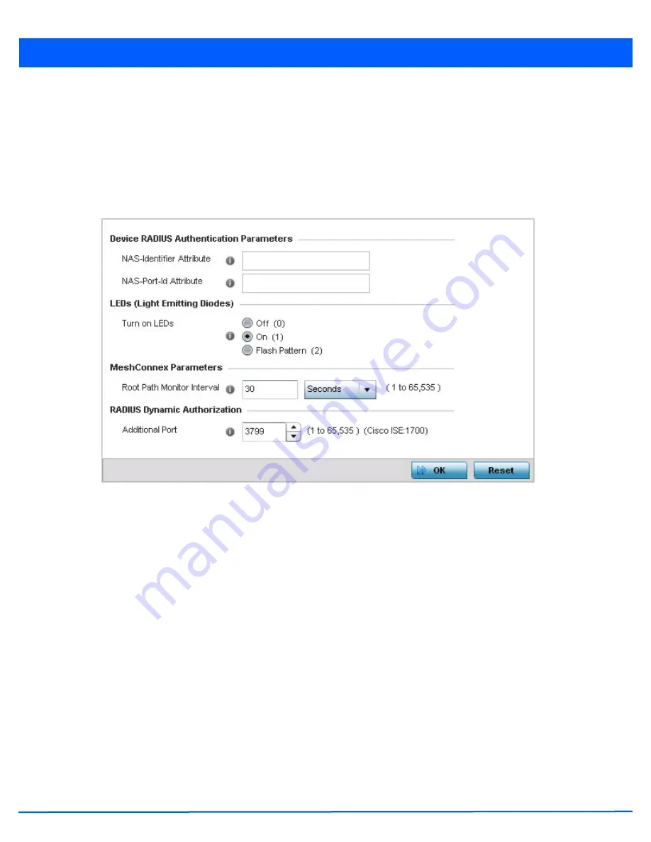
Figure 5-88
Advanced Profile Configuration - Miscellaneous screen
2. Set a
NAS-Identifier
Attribute up to 253 characters in length.
This is the RADIUS NAS-Identifier attribute that typically identifies the access point where a RADIUS message originates.
3. Set a
NAS-Port-Id Attribute
up to 253 characters in length.
This is the RADIUS NAS port ID attribute which identifies the port where a RADIUS message originates.
4. Select the
Turn on LEDs
radio button to ensure this access point’s LED remain continuously illuminated. Deployments such
as hospitals prefer to keep their wireless devices from having illuminating LEDs, as they have been reported to disturb their
patients. this setting, however, is enabled by default.
Select the
Flash Pattern
radio button to enable the access point to blink in a manner that is different from its operational
LED behavior. Enabling this option allows an administrator to validate that the access point has received its configuration
from its managing controller during staging. In the staging process, the administrator adopts the access point to a staging
controller to get an initial configuration before the access point is deployed at its intended location. Once the access point
has received its initial configuration, its LED blinks in a unique pattern to indicate that the initial configuration is complete.
5. Set the appropriate
Meshpoint Behavior
value by selecting either
external
(Fixed) or
vehicle-mounted
from the
drop-down menu. The value vehicle-mounted indicates that the mesh point is mobile. This feature is only available on an
AP7161 model access point.
6. Set the appropriate
Root Path Monitor Interval
value. This setting configures the frequency at which the path to the root
mesh point is monitored.
Summary of Contents for WiNG 5.4.2
Page 1: ...Motorola Solutions WiNG 5 4 2 ACCESS POINT SYSTEM REFERENCE GUIDE ...
Page 2: ......
Page 20: ...xvi WiNG 5 4 2 Access Point System Reference Guide ...
Page 24: ...1 4 WiNG 5 4 2 Access Point System Reference Guide ...
Page 36: ...2 12 WiNG 5 4 2 Access Point System Reference Guide ...
Page 54: ...3 18 WiNG 5 4 2 Access Point System Reference Guide ...
Page 358: ...6 2 WiNG 5 4 2 Access Point System Reference Guide Figure 6 1 Configuration Wireless menu ...
Page 462: ...6 106 WiNG 5 4 2 Access Point System Reference Guide ...
Page 474: ...7 12 WiNG 5 4 2 Access Point System Reference Guide ...
Page 509: ...9 5 Figure 9 2 Captive Portal Policy screen Basic Configuration tab ...
Page 572: ...11 12 WiNG 5 4 2 Access Point System Reference Guide ...
Page 626: ...12 54 WiNG 5 4 2 Access Point System Reference Guide ...
Page 790: ...A 2 WiNG 5 4 2 Access Point System Reference Guide ...
Page 835: ......


