5 - 107
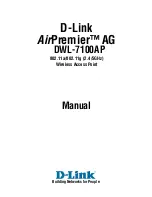
Figure 5-66
NAT Destination - Add screen
14. Set the following
Destination
configuration parameters:
Static NAT creates a permanent, one-to-one mapping between an address on an internal network and a perimeter or
external network. To share a Web server on a perimeter interface with the Internet, use static address translation to map
the actual address to a registered IP address. Static address translation hides the actual address of the server from users
on insecure interfaces. Casual access by unauthorized users becomes much more difficult. Static NAT requires a dedicated
address on the outside network for each host.
Protocol
Select the protocol for use with static translation.
TCP
,
UDP
and
Any
are the available
options.
Transmission Control Protocol
(TCP) is a transport layer protocol used by
applications requiring guaranteed delivery. It’s a sliding window protocol handling both
timeouts and retransmissions. TCP establishes a full duplex virtual connection between
two endpoints. Each endpoint is defined by an IP address and a TCP port number. The
User
Datagram Protocol
(UDP) offers only a minimal transport service, non-guaranteed
datagram delivery, and provides applications direct access to the datagram service of the
IP layer. UDP is used by applications not requiring the level of service of TCP or are using
communications services (multicast or broadcast delivery) not available from TCP. The
default setting is Any.
Destination IP
Enter the address used at the (source) end of the static NAT configuration. This address
(once translated) will not be exposed to the outside world when the translation address is
used to interact with the remote destination.
Destination Port
Use the spinner control to set the local port number used at the (source) end of the static
NAT configuration. The default value is port 1.
NAT IP
Enter the IP address of the matching packet to the specified value. The IP address modified
can be either
source
or
destination
based on the direction specified.
NAT Port
Enter the port number of the matching packet to the specified value. This option is valid
only if the direction specified is destination.
Summary of Contents for WiNG 5.4.2
Page 1: ...Motorola Solutions WiNG 5 4 2 ACCESS POINT SYSTEM REFERENCE GUIDE ...
Page 2: ......
Page 20: ...xvi WiNG 5 4 2 Access Point System Reference Guide ...
Page 24: ...1 4 WiNG 5 4 2 Access Point System Reference Guide ...
Page 36: ...2 12 WiNG 5 4 2 Access Point System Reference Guide ...
Page 54: ...3 18 WiNG 5 4 2 Access Point System Reference Guide ...
Page 358: ...6 2 WiNG 5 4 2 Access Point System Reference Guide Figure 6 1 Configuration Wireless menu ...
Page 462: ...6 106 WiNG 5 4 2 Access Point System Reference Guide ...
Page 474: ...7 12 WiNG 5 4 2 Access Point System Reference Guide ...
Page 509: ...9 5 Figure 9 2 Captive Portal Policy screen Basic Configuration tab ...
Page 572: ...11 12 WiNG 5 4 2 Access Point System Reference Guide ...
Page 626: ...12 54 WiNG 5 4 2 Access Point System Reference Guide ...
Page 790: ...A 2 WiNG 5 4 2 Access Point System Reference Guide ...
Page 835: ......