


CHAPTER 5.0 Functional Overview
5-34
CDS7324 (FORMERLY LSF-0819)
Rev. A
INSTALLATION & USER’S MANUAL
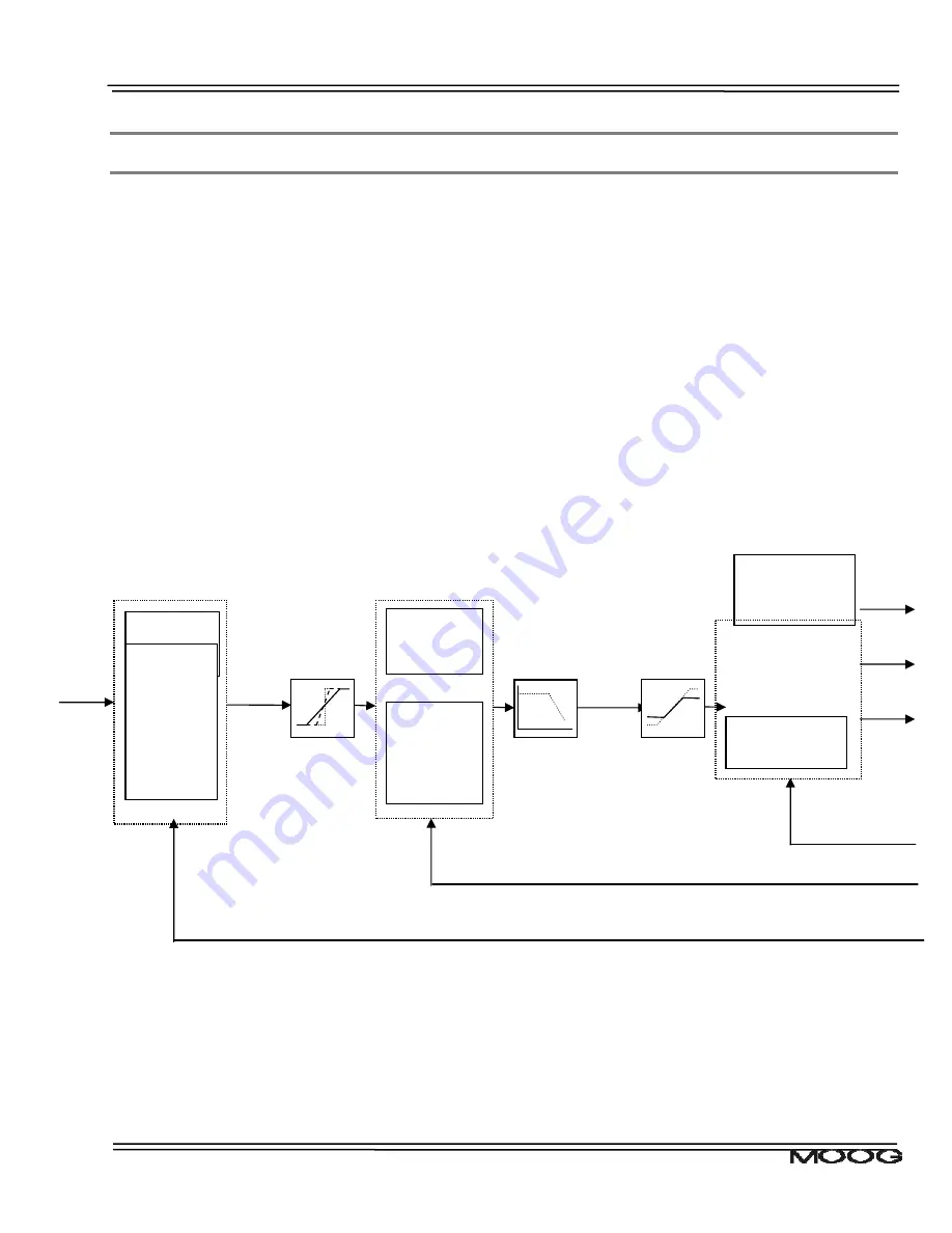
5.11 Control Loops
There are three loops that can be closed by DS2110, depending on the mode of operation of the drive. These
torque, velocity and position loops are nested inside each other, with the output of each compensator, being the
reference for the next inner loop.
•
In torque mode only the torque/current loop is closed, with a torque set-point or demand selected by the
user.
•
In velocity mode, the velocity compensator output is input to the current loop, with a velocity demand set
by the user.
•
In position mode, the position compensator output is input to the velocity loop, with the velocity
compensator output in turn input to the current loop. Again the user sets the position demand.
The diagram below shows the overall control loop structure.
Figure 5.4 : Overall Drive Control Loop Structure
The following sections of the manual will describe in more detail each of the blocks listed above, beginning from
left to right.
Filter (LP, HP,
Actual
Velocity
Actual
Position
PWM_C
PWM_A
PWM_B
Actual
Currents
Torque
Demand
Acceleration
Velocity Compensator
Velocity
Demand
Position
Demand
Position Compensator
PI comp
(Kp, Ki)
Time
Optimal
comp (Kp,
Ka, Ki)
PI comp
(Kp, Ki)
I-PI comp
(Kp, Ki,
Kie)
Current Loop
Thermal / Current
d and q comp,
α
and
β
trans
Predictive
Current Loop


