


CHAPTER 5.0 Functional Overview
5-13
CDS7324 (FORMERLY LSF-0819)
Rev. A
INSTALLATION & USER’S MANUAL
5.5 Resolver
Input
The resolver input allows the connection of various resolvers for drive position feedback, velocity feedback or for
motor commutation (rotor angle feedback).
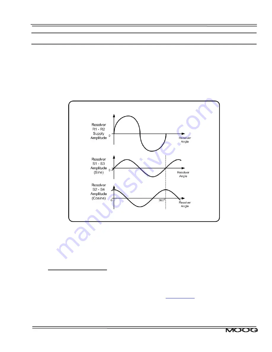
The drive supplies the resolver with a sinusoidal reference signal (R1 - R2). The resolver output signals have the
same frequency as the reference but the amplitude changes depending on the rotational angle. The output
signals are normally referred to as Sine (S1 - S3) and Cosine (S2 - S4). By measuring the amplitude of both
Sine and Cosine Signals and applying an arctan function the drive can determine the rotor angle of the motor.
Figure 5.2: Resolver Signal Amplitude
The picture shows the amplitude of the Sine and Cosine signals depending on the rotation angle of the resolver.
Normally the reference voltage is about 16 Vpp and the maximum Sine or Cosine voltage is about 2 Volts. The
frequency is 8 kHz.
5.5.1 Resolver
Configuration
5.5.1.1
Number Resolver poles
The number of resolver pole pairs determines the number of full Sine or Cosine amplitude cycles per full
mechanical revolution. In order to function properly, the parameter
resolver_poles
(Field Number 1037) has to
be set to the number of resolver poles (pole pairs multiplied by 2). Refer to the motor manufacturers datasheet
for further information. For standard motors in the motor database this parameter is configured as part of the
motor parameter download.


