8 - 36 8 - 36
8 FUNCTIONS
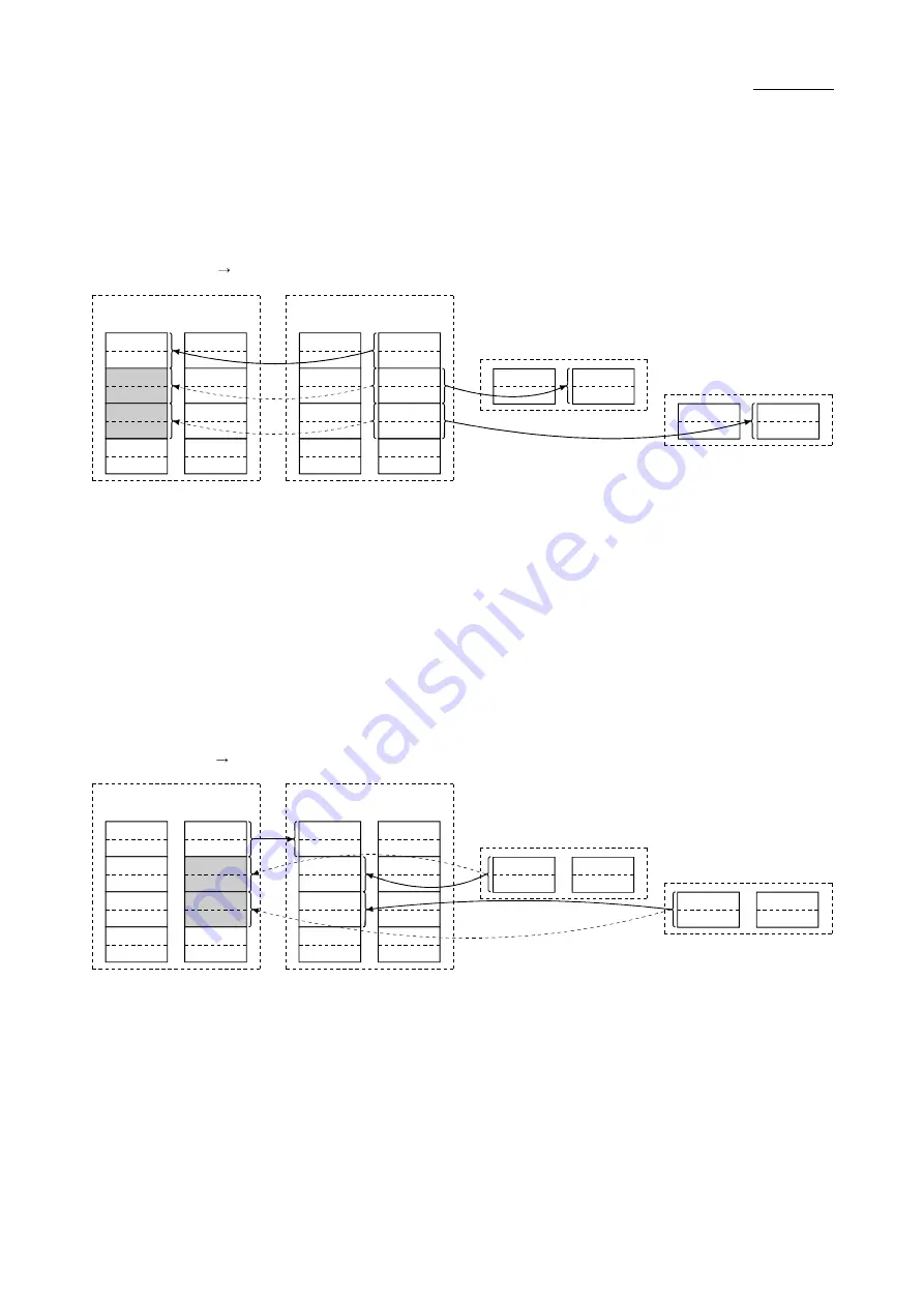
(c) When the master station returns to system operation and the standby master
station is controlling the data link
1) Standby master station output
RY00 to RY0F
RY10 to RY1F
RY20 to RY2F
RY30 to RY3F
RY40 to RY4F
RY50 to RY5F
RX00 to RX0F
RX10 to RX1F
RX20 to RX2F
RX30 to RX3F
RX40 to RX4F
RX50 to RX5F
Master station (standby)
Station number 0 1
Occupies 1 station
RY00 to RY0F
RY10 to RY1F
RY20 to RY2F
RY30 to RY3F
RY40 to RY4F
RY50 to RY5F
RX00 to RX0F
RX10 to RX1F
RX20 to RX2F
RX30 to RX3F
RX40 to RX4F
RX50 to RX5F
Y00 to Y0F
Y10 to Y1F
X00 to X0F
X10 to X1F
Remote I/O station
Station number 2
Occupies 1 station
Y00 to Y0F
Y10 to Y1F
X00 to X0F
X10 to X1F
Remote I/O station
Station number 3
Occupies 1 station
Standby master station
(controlling)
Station number 0
Remote
output RY
Remote
input RX
Remote
output RY
Remote
input RX
Data sent from the standby master station to the remote input RX and
remote register RWr in the master station (shown by the shaded areas in
the figure above) is used as output data when the standby master
station becomes faulty; it should be saved in another device using the
program.
When the standby master station becomes faulty, the saved data is
transferred to the remote output RY and remote register RWw in the
master station using the program.
2) Standby master station input
RY00 to RY0F
RY10 to RY1F
RY20 to RY2F
RY30 to RY3F
RY40 to RY4F
RY50 to RY5F
RX00 to RX0F
RX10 to RX1F
RX20 to RX2F
RX30 to RX3F
RX40 to RX4F
RX50 to RX5F
RY00 to RY0F
RY10 to RY1F
RY20 to RY2F
RY30 to RY3F
RY40 to RY4F
RY50 to RY5F
RX00 to RX0F
RX10 to RX1F
RX20 to RX2F
RX30 to RX3F
RX40 to RX4F
RX50 to RX5F
Y00 to Y0F
Y10 to Y1F
X00 to X0F
X10 to X1F
Y00 to Y0F
Y10 to Y1F
X00 to X0F
X10 to X1F
Master station (standby)
Station number 0 1
Occupies 1 station
Remote I/O station
Station number 2
Occupies 1 station
Remote I/O station
Station number 3
Occupies 1 station
Standby master station
(controlling)
Station number 0
Remote
output RY
Remote
input RX
Remote
output RY
Remote
input RX
Data sent to the remote output RY and remote register RWw in the
master station is being used as input data by the master station when
local stations are operating; thus, it does not need to be saved in another
device.
Summary of Contents for L26CPU-BT
Page 1: ......
Page 2: ......
Page 32: ...3 5 3 5 3 SPECIFICATIONS ...
Page 51: ...4 2 4 2 4 PROCEDURE BEFORE OPERATION 4 ...
Page 61: ...6 4 6 4 6 INSTALLATION AND CONNECTION ...
Page 63: ...6 6 6 6 6 INSTALLATION AND CONNECTION 8 The connection method is shown below ...
Page 70: ...6 13 6 13 6 INSTALLATION AND CONNECTION ...
Page 72: ...6 15 6 15 6 INSTALLATION AND CONNECTION ...
Page 139: ...8 33 8 33 8 FUNCTIONS ...
Page 151: ...8 45 8 45 8 FUNCTIONS ...
Page 246: ...11 9 11 9 11 EXAMPLE OF COMMUNICATION BETWEEN THE MASTER STATION AND REMOTE DEVICE STATIONS ...
Page 311: ...13 2 13 2 13 COMMUNICATION BETWEEN THE MASTER STATION AND INTELLIGENT DEVICE STATIONS MEMO 13 ...
Page 321: ...14 10 14 10 14 EXAMPLE OF COMMUNICATION WHEN MOUNTING MODULES ON THE HEAD MODULE ...
Page 326: ...15 5 15 5 15 TROUBLESHOOTING To the next page ...
Page 327: ...15 6 15 6 15 TROUBLESHOOTING To the next page ...
Page 328: ...15 7 15 7 15 TROUBLESHOOTING ...
Page 329: ...15 8 15 8 15 TROUBLESHOOTING 2 Troubleshooting by status logging ...
Page 436: ...App 72 App 72 APPENDIXES 7 Operating procedure of the transmission speed test ...
Page 439: ...App 75 App 75 APPENDIXES MEMO ...
Page 447: ......
Page 448: ......
Page 449: ......


