A - 8
(4) Power supply
(a) Operate the servo amplifier to meet the requirements of the overvoltage category II set forth in
IEC60664-1. For this purpose, a reinforced insulating transformer conforming to the IEC or EN
Standard should be used in the power input section.
(b) When supplying interface power from external, use a 24VDC power supply which has been
insulation-reinforced in I/O.
(5) Grounding
(a) To prevent an electric shock, always connect the protective earth (PE) terminals (marked ) of the
servo amplifier to the protective earth (PE) of the control box.
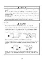
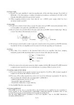
(b) Do not connect two ground cables to the same protective earth (PE) terminal (marked ). Always
connect the cables to the terminals one-to-one.
PE terminals
PE terminals
(c) If a leakage current breaker is used to prevent an electric shock, the protective earth (PE) terminals
(marked ) of the servo amplifier must be connected to the corresponding earth terminals.
(6) Wiring
(a) The cables to be connected to the terminal block of the servo amplifier must have crimping
terminals provided with insulating tubes to prevent contact with adjacent terminals.
Crimping terminal
Insulating tube
Cable
(b) Use the servo motor side power connector which complies with the EN Standard. The EN Standard
compliant power connector sets are available from us as options. (Refer to section 14.1.4)
(7) Auxiliary equipment and options
(a) The circuit breaker and magnetic contactor used should be the EN or IEC standard-compliant
products of the models described in section 14.2.2.
(b) The sizes of the cables described in section 14.2.1 meet the following requirements. To meet the
other requirements, follow Table 5 and Appendix C in EN60204-1.
Ambient temperature: 40 (104) [ ( )]
Sheath: PVC (polyvinyl chloride)
Installed on wall surface or open table tray
(c) Use the EMC filter for noise reduction.
(8) Performing EMC tests
When EMC tests are run on a machine/device into which the servo amplifier has been installed, it
must conform to the electromagnetic compatibility (immunity/emission) standards after it has
satisfied the operating environment/electrical equipment specifications.
For the other EMC directive guidelines on the servo amplifier, refer to the EMC Installation
Guidelines (IB(NA)67310).
Summary of Contents for MR-J2S-10CP
Page 11: ...A 10 MEMO ...
Page 19: ...8 MEMO ...
Page 45: ...1 26 1 FUNCTIONS AND CONFIGURATION MEMO ...
Page 181: ...6 20 6 MR Configurator SERVO CONFIGURATION SOFTWARE MEMO ...
Page 207: ...7 26 7 DISPLAY AND OPERATION MEMO ...
Page 219: ...8 12 8 GENERAL GAIN ADJUSTMENT MEMO ...
Page 229: ...9 10 9 SPECIAL ADJUSTMENT FUNCTIONS MEMO ...
Page 231: ...10 2 10 INSPECTION MEMO ...
Page 249: ...12 8 12 OUTLINE DIMENSION DRAWINGS MEMO ...
Page 257: ...13 8 13 CHARACTERISTICS MEMO ...


