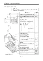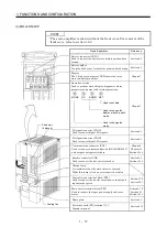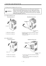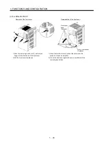
2 - 2
2. INSTALLATION
2.2 Installation direction and clearances
CAUTION
Do not hold the front cover to transport the servo amplifier. The servo amplifier
may drop.
The equipment must be installed in the specified direction. Otherwise, a fault may
occur.
Leave specified clearances between the servo amplifier and control box inside
walls or other equipment.
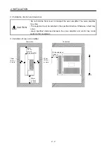
(1) Installation of one servo amplifier
Control box
Control box
10mm
(0.4 in.)
or more
10mm
(0.4 in.)
or more
40mm
(1.6 in.)
or more
40mm
(1.6 in.)
or more
Wiring clearance
70mm
(2.8 in.)
Servo amplifier
Up
Down
Summary of Contents for MR-J2S-10CP
Page 11: ...A 10 MEMO ...
Page 19: ...8 MEMO ...
Page 45: ...1 26 1 FUNCTIONS AND CONFIGURATION MEMO ...
Page 181: ...6 20 6 MR Configurator SERVO CONFIGURATION SOFTWARE MEMO ...
Page 207: ...7 26 7 DISPLAY AND OPERATION MEMO ...
Page 219: ...8 12 8 GENERAL GAIN ADJUSTMENT MEMO ...
Page 229: ...9 10 9 SPECIAL ADJUSTMENT FUNCTIONS MEMO ...
Page 231: ...10 2 10 INSPECTION MEMO ...
Page 249: ...12 8 12 OUTLINE DIMENSION DRAWINGS MEMO ...
Page 257: ...13 8 13 CHARACTERISTICS MEMO ...


