Print data
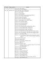
*Manual number
Revision
Jul., 2006
SH(NA)030017-F Section 7.2.3: Correction of description for command position
Section 8.3.1 (1) (a): Addition of parameter in Table
Section 8.4 (2): Correction of description for Step 5
Section 11.2.2: Correction of name for Al. 17
Section 11.2.3: Correction of description for Al. 90
Section 12.2 (1) (b): Correction of error in dimensions
Section 14.1.1 (2): Correction of formula in Table
Section 14.1.1 (4): Sentence reexamination
Section 14.1.5 (3): Addition of pin No. in figure
Section 14.1.7 (2): Correction of signal name for CN3-1 pin
Section 14.1.9: POINT reexamination
Section 15.12.3 (2): Correction of POINT sentence
Section 15.12.5: Sentence addition
Section 15.12.12: Description reexamination
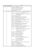
Sep., 2007 SH(NA)-030017-G Safety Instructions
1. To prevent electric shock: Partial change of sentence
2. To prevent fire: Partial change of sentence
4. Additional Instructions
(2) Wiring: Addition of sentence
Section 1.1.1: Addition of Note
Section 1.6.2: WARNING Change of sentence
Section 1.7: Addition of Note
Chapter 3: WARNING Change of sentence
Section 3.6.2 (2): Addition of sentence Addition of Note
Section 3.6.2 (6): Addition of Note
Section 3.7: CAUTION Change of sentence
Section 3.9 (3): Change of timing chart
Section 4.4.5 (3): Addition of Note
Section 4.4.8: POINT Change of sentence
Section 4.5: POINT addition
Section 4.5 (5): CAUTION Change of sentence
Section 5.1.2 (2): Partial change of parameter No.0
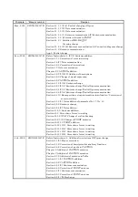
Chapter 10: WARNING Change of sentence
Section 11.2: Addition of AL. 20 Definition
Change of sentence in AL. 32. Definition
Change of sentence in AL. 33. Definition
Addition of Cause 6 for AL. 50
Change of sentence in AL. 51. Definition
Section 11.3: New addition
Chapter 14: WARNING Change of sentence
Section 14.1.1 (3): Change of parameter No.0 definition
Section 14.1.1 (5) (b), (c): Change of outline dimension drawing
Section 14.1.2: Overall change to FR-BU2
Section 14.1.4: Change of some connectors to RoHS compatible products
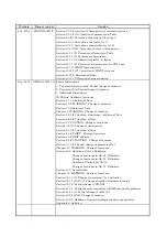
Section 14.2.1 (1): Partial change of table 14.2
Section 14.2.6 (2) (d): Change of sentence
Section 14.2.8: Addition of connection diagram and surge protector
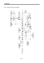
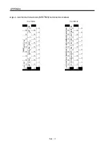
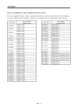
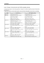
Appendix 6: Addition
Summary of Contents for MR-J2S-10CP
Page 11: ...A 10 MEMO ...
Page 19: ...8 MEMO ...
Page 45: ...1 26 1 FUNCTIONS AND CONFIGURATION MEMO ...
Page 181: ...6 20 6 MR Configurator SERVO CONFIGURATION SOFTWARE MEMO ...
Page 207: ...7 26 7 DISPLAY AND OPERATION MEMO ...
Page 219: ...8 12 8 GENERAL GAIN ADJUSTMENT MEMO ...
Page 229: ...9 10 9 SPECIAL ADJUSTMENT FUNCTIONS MEMO ...
Page 231: ...10 2 10 INSPECTION MEMO ...
Page 249: ...12 8 12 OUTLINE DIMENSION DRAWINGS MEMO ...
Page 257: ...13 8 13 CHARACTERISTICS MEMO ...

