3 - 5
3. SIGNALS AND WIRING
3.3.2 Signal (devices) explanations
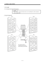
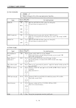
(1) I/O devices
POINT
The devices not indicated in the Connector Pin No. field of the I/O devices
can be assigned to the connector CN1A/CN1B using the MR Configurator
(servo configuration software).
(a) Pins whose devices can be changed
Refer to section 3.6.2 for the I/O interfaces (symbols in the I/O Division field in the table) of the
corresponding connector pins.
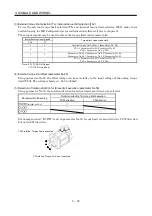
Pin type
Connector pin No.
I/O division
Device in initial status
CN1B-5
Point table No. selection 1 (DI0)
CN1B-14
Point table No. selection 2 (DI1)
CN1A-8 Proximity
dog
(DOG)
CN1B-15 Servo-on
(SON)
CN1B-16
Forward rotation stroke end (LSP)
CN1B-17
Reverse rotation stroke end (LSN)
CN1B-7
Automatic/manual selection (MD0)
CN1B-8
Forward rotation start (ST1)
Input-only pins
CN1B-9
DI-1
Reverse rotation start (ST2)
I/O pin
CN1A-19
DI-1 or DO-1
No device has been assigned in the initial
status. You can assign an I/O device using
the MR Configurator (servo configuration
software).
CN1B-4 Rough
match
(CPO)
CN1B-6 Movement
finish
(MEND)
CN1B-18 Trouble
(ALM)
CN1B-19 Ready
(RD)
Output-only pins
CN1A-18
DO-1
Home position return completion(ZP)
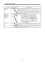
(b) Input devices
Device name
Devices
symbol
Connector
pin No.
Functions/Applications
Forced stop
EMG
When EMG-SG are opened, the servo amplifier is placed in the forced stop status,
the servo switches off, and the dynamic brake is operated to bring the servo motor
to a sudden stop.
Short EMG-SG in the forced stop status to cancel the forced stop status.
Servo-on SON
CN1B
15
Connect SON-SG to switch on the base circuit and make the servo amplifier ready
to operate (servo-on).
Disconnect SON-SG to shut off the base circuit and coast the servo motor (servo-
off) .
Reset
RES
Disconnect RES-SG for more than 50ms to reset the alarm.
Some alarms cannot be deactivated by the reset signal. Refer to section 11.2.1
If RES-SG are shorted in no alarm status, the base circuit is not shut off.
Set " 1 " in parameter No. 55 to shut off the base circuit.
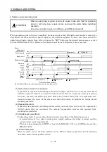
Since this device is not designed for stopping. Do not switch it on during operation.
Summary of Contents for MR-J2S-10CP
Page 11: ...A 10 MEMO ...
Page 19: ...8 MEMO ...
Page 45: ...1 26 1 FUNCTIONS AND CONFIGURATION MEMO ...
Page 181: ...6 20 6 MR Configurator SERVO CONFIGURATION SOFTWARE MEMO ...
Page 207: ...7 26 7 DISPLAY AND OPERATION MEMO ...
Page 219: ...8 12 8 GENERAL GAIN ADJUSTMENT MEMO ...
Page 229: ...9 10 9 SPECIAL ADJUSTMENT FUNCTIONS MEMO ...
Page 231: ...10 2 10 INSPECTION MEMO ...
Page 249: ...12 8 12 OUTLINE DIMENSION DRAWINGS MEMO ...
Page 257: ...13 8 13 CHARACTERISTICS MEMO ...

