14 - 20
14. OPTIONS AND AUXILIARY EQUIPMENT
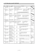
No. Product
Model
Description
Application
9) Control
signal
connector set
MR-J2CN1 Connector:
10120-3000PE
Shell kit: 10320-52F0-008
(3M or equivalent)
Qty: 2 each
Connector: HIF3BA-20D-2.54R
(Hirose Electric)
Connector: 10120-6000EL
Shell kit: 10320-3210-000
(3M or equivalent)
10) Junction
terminal block
cable
MR-J2TBL M
Refer to
section14.1.5.
For junction
terminal
block
connection
11) Junction
terminal block
MR-TB20
Refer to section 14.1.5.
Connector: 10120-6000EL
Shell kit: 10320-3210-000
(3M or equivalent)
Connector: 10120-6000EL
Shell kit: 10320-3210-000
(3M or equivalent)
12) Bus
cable
MR-J2HBUS M
Refer to
section14.1.6.
For
maintenance
junction
card
connection
13) Maintenance
junction card
MR-J2CN3TM
Refer to section 14.1.6.
Connector: 10120-6000EL
Shell kit: 10320-3210-000
(3M or equivalent)
Connector: DE-9SF-N
Case: DE-C1-J6-S6
(JAE)
14) Communication
cable
MR-CPCATCBL3M
Refer to (3) of this
section.
For
connection
with PC-AT-
compatible
personal
computer
15) Power supply
connector set
MR-PWCNS1
Refer to the Servo
Motor Instruction
Manual.
Connector: CE05-6A22-23SD-D-BSS
Cable clamp:CE3057-12A-2-D
(DDK)
16) Power supply
connector set
MR-PWCNS2
Refer to the Servo
Motor Instruction
Manual.
Connector: CE05-6A24-10SD-D-BSS
Cable clamp: CE3057-16A-2-D
(DDK)
17) Power supply
connector set
MR-PWCNS3
Refer to the Servo
Motor Instruction
Manual.
Plug: CE05-6A32-17SD-D-BSS
Cable clamp: CE3057-20A-1-D
(DDK)
Must be
used to
comply with
the EN
Standard.
IP65 IP67
18) Brake
connector
set
MR-BKCN
Refer to the Servo
Motor Instruction
Manual.
Plug: D/MS3106A10SL-4S (D190) (DDK)
Cable connector: YS010-5-8 (Daiwa Dengyo)
EN
Standard-
compliant
IP65 IP67
19) Power supply
connector set
MR-PWCNK1
Refer to the Servo
Motor Instruction
Manual.
Plug: 5559-04P-210
Terminal: 5558PBT3L (For AWG16)(6 pcs.)
(Molex)
IP20
20) Power supply
connector set
MR-PWCNK2
Plug: 5559-06P-210
Terminal: 5558PBT3L (For AWG16)(8 pcs.)
(Molex)
For motor
with brake
IP20
Summary of Contents for MR-J2S-10CP
Page 11: ...A 10 MEMO ...
Page 19: ...8 MEMO ...
Page 45: ...1 26 1 FUNCTIONS AND CONFIGURATION MEMO ...
Page 181: ...6 20 6 MR Configurator SERVO CONFIGURATION SOFTWARE MEMO ...
Page 207: ...7 26 7 DISPLAY AND OPERATION MEMO ...
Page 219: ...8 12 8 GENERAL GAIN ADJUSTMENT MEMO ...
Page 229: ...9 10 9 SPECIAL ADJUSTMENT FUNCTIONS MEMO ...
Page 231: ...10 2 10 INSPECTION MEMO ...
Page 249: ...12 8 12 OUTLINE DIMENSION DRAWINGS MEMO ...
Page 257: ...13 8 13 CHARACTERISTICS MEMO ...

