5 - 15
5. PARAMETERS
Class No. Symbol
Name and Function
Initial
value
Unit
Setting
range
E
xpa
n
si
on
pa
ra
m
et
ers
2
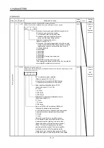
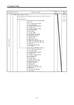
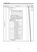
59 *OPA Function selection A
Used to select the alarm code.
Setting of alarm code output
Connector pins
Set
value
CN1B-19
CN1A-18
CN1A-19
0
1
88888
AL.12
AL.13
AL.15
AL.17
AL.8A
AL.8E
AL.30
AL.45
AL.50
AL.51
AL.24
AL.32
AL.31
AL.35
Name
Watchdog
Memory error 1
Clock error
Memory error 2
Board error 2
Serial communication time-out error
Serial communication error
Regenerative error
Main circuit device overheat
Overload 1
Overload 2
Main circuit
Overcurrent
Overspeed
Command pulse frequency error
Error excessive
Alarm
display
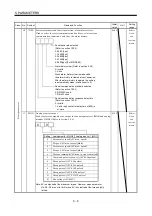
(Note) Alarm code
CN1B
pin 19
0
0
0
0
1
CN1A
pin 18
0
0
1
1
0
1
CN1A
pin 19
1
0
1
0
AL.19 Memory error 3
AL.37 Parameter error
AL.33 Overvoltage
AL.46 Servo motor overheat
AL.10 Undervoltage
1
0
0
AL.16
AL.20
Encoder error 1
Encoder error 2
1
1
0
Note: 0:Pin-SG off (open)
1:Pin-SG on (short)
AL.1A
AL.25
Motor combination error
Absolute position erase
Alarm code is output at alarm occurrence.
Signals assigned to corresponding pins are output.
CW direction
CCW direction
Setting
0
Rotation direction in which torque limit is made valid
1
2
0
0
AL.52
AL.61 Home operation alarm
0000
Refer to
Name
and
function
column.
Summary of Contents for MR-J2S-10CP
Page 11: ...A 10 MEMO ...
Page 19: ...8 MEMO ...
Page 45: ...1 26 1 FUNCTIONS AND CONFIGURATION MEMO ...
Page 181: ...6 20 6 MR Configurator SERVO CONFIGURATION SOFTWARE MEMO ...
Page 207: ...7 26 7 DISPLAY AND OPERATION MEMO ...
Page 219: ...8 12 8 GENERAL GAIN ADJUSTMENT MEMO ...
Page 229: ...9 10 9 SPECIAL ADJUSTMENT FUNCTIONS MEMO ...
Page 231: ...10 2 10 INSPECTION MEMO ...
Page 249: ...12 8 12 OUTLINE DIMENSION DRAWINGS MEMO ...
Page 257: ...13 8 13 CHARACTERISTICS MEMO ...


