1
CONTENTS
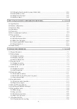
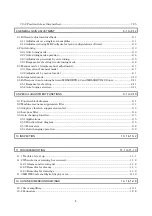
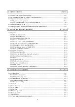
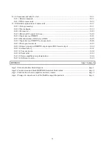
1. FUNCTIONS AND CONFIGURATION
1- 1 to 1-26
1.1 Introduction.............................................................................................................................................. 1- 1
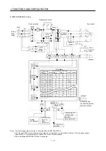
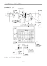
1.1.1 Function block diagram ................................................................................................................... 1- 1
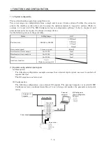
1.1.2 System configuration........................................................................................................................ 1- 4
1.1.3 I/O devices ......................................................................................................................................... 1- 9
1.2 Servo amplifier standard specifications ............................................................................................... 1-10
1.3 Function list ............................................................................................................................................ 1-12
1.4 Model code definition ............................................................................................................................. 1-13
1.5 Combination with servo motor.............................................................................................................. 1-14
1.6 Structure.................................................................................................................................................. 1-15
1.6.1 Part names ....................................................................................................................................... 1-15
1.6.2 Removal and reinstallation of the front cover .............................................................................. 1-19
1.7 Servo system with auxiliary equipment............................................................................................... 1-21
2. INSTALLATION
2- 1 to 2- 4
2.1 Environmental conditions ...................................................................................................................... 2- 1
2.2 Installation direction and clearances .................................................................................................... 2- 2
2.3 Keep out foreign materials ..................................................................................................................... 2- 3
2.4 Cable stress .............................................................................................................................................. 2- 4
3. SIGNALS AND WIRING
3- 1 to 3-42
3.1 Standard connection example ................................................................................................................ 3- 2
3.2 Internal connection diagram of servo amplifier ................................................................................... 3- 3
3.3 I/O signals................................................................................................................................................. 3- 4
3.3.1 Connectors and signal arrangements............................................................................................. 3- 4
3.3.2 Signal (devices) explanations .......................................................................................................... 3- 5
3.4 Detailed description of signals (devices) .............................................................................................. 3-13
3.4.1 Forward rotation start Reverse rotation start Temporary stop/restart................................. 3-13
3.4.2 Movement finish Rough match In position............................................................................... 3-14
3.4.3 Override ............................................................................................................................................ 3-16
3.4.4 Torque limit...................................................................................................................................... 3-17
3.5 Alarm occurrence timing chart ............................................................................................................. 3-19
3.6 Interfaces................................................................................................................................................. 3-20
3.6.1 Common line .................................................................................................................................... 3-20
3.6.2 Detailed description of the interfaces ............................................................................................ 3-21
3.7 Input power supply circuit..................................................................................................................... 3-25
3.7.1 Connection example ........................................................................................................................ 3-25
3.7.2 Terminals.......................................................................................................................................... 3-27
3.7.3 Power-on sequence........................................................................................................................... 3-28
3.8 Connection of servo amplifier and servo motor ................................................................................... 3-29
3.8.1 Connection instructions .................................................................................................................. 3-29
3.8.2 Connection diagram ........................................................................................................................ 3-29
3.8.3 I/O terminals .................................................................................................................................... 3-31
3.9 Servo motor with electromagnetic brake ............................................................................................. 3-33
Summary of Contents for MR-J2S-10CP
Page 11: ...A 10 MEMO ...
Page 19: ...8 MEMO ...
Page 45: ...1 26 1 FUNCTIONS AND CONFIGURATION MEMO ...
Page 181: ...6 20 6 MR Configurator SERVO CONFIGURATION SOFTWARE MEMO ...
Page 207: ...7 26 7 DISPLAY AND OPERATION MEMO ...
Page 219: ...8 12 8 GENERAL GAIN ADJUSTMENT MEMO ...
Page 229: ...9 10 9 SPECIAL ADJUSTMENT FUNCTIONS MEMO ...
Page 231: ...10 2 10 INSPECTION MEMO ...
Page 249: ...12 8 12 OUTLINE DIMENSION DRAWINGS MEMO ...
Page 257: ...13 8 13 CHARACTERISTICS MEMO ...


