15 - 2
15. COMMUNICATION FUNCTIONS
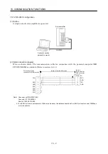
15.1.2 RS-232C configuration
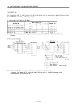
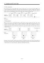
(1) Outline
A single axis of servo amplifier is operated.
CHARGE
MITSUBISHI
RS-232C
Controller such as
personal computer
Servo amplifier
To CN3
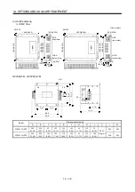
(2) Cable connection diagram
Wire as shown below. The communication cable for connection with the personal computer (MR-
CPCATCBL3M) is available. (Refer to section 14.1.4.)
Personal computer
connector D-SUB9 (socket)
TXD
RXD
GND
RTS
CTS
3
2
5
7
8
DSR
DTR
6
4
(Note 1)
Servo amplifier
CN3 connector
TXD
GND
RXD
GND
FG
12
11
2
1
Plate
(Note 2) 15m (49.2ft) or less
Note 1. Connector set MR-J2CN1 (3M)
Connector: 10120-6000EL
Shell kit: 10320-3210-000
2. 15m (49.2ft) or less in environment of little noise. However, this distance should be 3m (9.84ft) or less for use at 38400bps
or more baud rate.
Summary of Contents for MR-J2S-10CP
Page 11: ...A 10 MEMO ...
Page 19: ...8 MEMO ...
Page 45: ...1 26 1 FUNCTIONS AND CONFIGURATION MEMO ...
Page 181: ...6 20 6 MR Configurator SERVO CONFIGURATION SOFTWARE MEMO ...
Page 207: ...7 26 7 DISPLAY AND OPERATION MEMO ...
Page 219: ...8 12 8 GENERAL GAIN ADJUSTMENT MEMO ...
Page 229: ...9 10 9 SPECIAL ADJUSTMENT FUNCTIONS MEMO ...
Page 231: ...10 2 10 INSPECTION MEMO ...
Page 249: ...12 8 12 OUTLINE DIMENSION DRAWINGS MEMO ...
Page 257: ...13 8 13 CHARACTERISTICS MEMO ...


