11 - 5
11. TROUBLESHOOTING
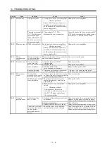
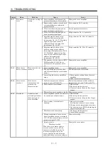
Display Name
Definition
Cause
Action
1. Wrong setting of parameter No. 0 Set correctly.
2. Built-in regenerative resistor or
regenerative option is not
connected.
Connect correctly
3. High-duty operation or continuous
regenerative operation caused the
permissible regenerative power of
the regenerative option to be
exceeded.
Checking method
Call the status display and check
the regenerative load ratio.
1. Reduce the frequency of positioning.
2. Use the regenerative option of larger
capacity.
3. Reduce the load.
4. Power supply voltage is abnormal.
MR-J2S- CP:260VAC or more
MR-J2S- CP1:135VAC or more
Review power supply
Permissible
regenerative power
of the built-in
regenerative resistor
or regenerative
option is exceeded.
5. Built-in regenerative resistor or
regenerative option faulty.
Change servo amplifier or regenerative
option.
AL.30 Regenerative
error
Regenerative
transistor fault
6. Regenerative transistor faulty.
Checking method
1) The regenerative option has
overheated abnormally.
2) The alarm occurs even after
removal of the built-in
regenerative resistor or
regenerative option.
Change the servo amplifier.
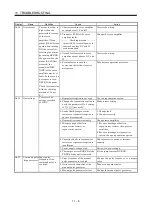
1. Input command pulse frequency
exceeded the permissible
instantaneous speed frequency.
Set command pulses correctly.
2. Small acceleration/deceleration
time constant caused overshoot to
be large.
Increase acceleration/deceleration time
constant.
3. Servo system is instable to cause
overshoot.
1. Re-set servo gain to proper value.
2. If servo gain cannot be set to proper
value.
1) Reduce load inertia moment ratio; or
2) Reexamine acceleration/
deceleration time constant.
4. Electronic gear ratio is large
(parameters No. 4, 5)
Set correctly.
AL.31 Overspeed
Speed has exceeded
the instantaneous
permissible speed.
5. Encoder faulty.
Change the servo motor.
Summary of Contents for MR-J2S-10CP
Page 11: ...A 10 MEMO ...
Page 19: ...8 MEMO ...
Page 45: ...1 26 1 FUNCTIONS AND CONFIGURATION MEMO ...
Page 181: ...6 20 6 MR Configurator SERVO CONFIGURATION SOFTWARE MEMO ...
Page 207: ...7 26 7 DISPLAY AND OPERATION MEMO ...
Page 219: ...8 12 8 GENERAL GAIN ADJUSTMENT MEMO ...
Page 229: ...9 10 9 SPECIAL ADJUSTMENT FUNCTIONS MEMO ...
Page 231: ...10 2 10 INSPECTION MEMO ...
Page 249: ...12 8 12 OUTLINE DIMENSION DRAWINGS MEMO ...
Page 257: ...13 8 13 CHARACTERISTICS MEMO ...

