3 - 10
3. SIGNALS AND WIRING
Device name
Devices
symbol
Connector
pin No.
Functions/Applications
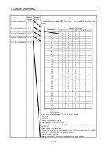
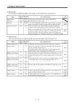
Point table No. output 1
PT0
As soon as Movement finish (MEND) turns on, the point table No. is output as a 5-
bit code.
(Note) Output signal
Point table No. output 2
PT1
Point table No.
PT4 PT3 PT2 PT1 PT0
0 0 0 0 0
Point table No. output 3
PT2
1
0 0 0 0 1
2
0 0 0 1 0
Point table No. output 4
PT3
3
0 0 0 1 1
4
0 0 1 0 0
5
0 0 1 0 1
6
0 0 1 1 0
7
0 0 1 1 1
8
0 1 0 0 0
9
0 1 0 0 1
10
0 1 0 1 0
11
0 1 0 1 1
12
0 1 1 0 0
13
0 1 1 0 1
14
0 1 1 1 0
15
0 1 1 1 1
16
1 0 0 0 0
17
1 0 0 0 1
18
1 0 0 1 0
19
1 0 0 1 1
20
1 0 1 0 0
21
1 0 1 0 1
22
1 0 1 1 0
23
1 0 1 1 1
24
1 1 0 0 0
25
1 1 0 0 1
26
1 1 0 1 0
27
1 1 0 1 1
28
1 1 1 0 0
29
1 1 1 0 1
30
1 1 1 1 0
31
1 1 1 1 1
Note. 0: DI-SG open
1: DI-SG shorted
Point table No. output 5
PT4
In any of the following states, PT0 to PT4-SG are opened.
Power on
Servo off
During home position return
Home position return completion
In any of the following states, PT0 to PT4 maintain the status (shorted/open) prior
to a change.
At operation mode changing
When the automatic/manual selection device (MD0) is turned from OFF to ON or
from ON to OFF to switch the operation mode.
During manual operation
During execution of automatic positioning to the home position
Summary of Contents for MR-J2S-10CP
Page 11: ...A 10 MEMO ...
Page 19: ...8 MEMO ...
Page 45: ...1 26 1 FUNCTIONS AND CONFIGURATION MEMO ...
Page 181: ...6 20 6 MR Configurator SERVO CONFIGURATION SOFTWARE MEMO ...
Page 207: ...7 26 7 DISPLAY AND OPERATION MEMO ...
Page 219: ...8 12 8 GENERAL GAIN ADJUSTMENT MEMO ...
Page 229: ...9 10 9 SPECIAL ADJUSTMENT FUNCTIONS MEMO ...
Page 231: ...10 2 10 INSPECTION MEMO ...
Page 249: ...12 8 12 OUTLINE DIMENSION DRAWINGS MEMO ...
Page 257: ...13 8 13 CHARACTERISTICS MEMO ...


