14 - 37
14. OPTIONS AND AUXILIARY EQUIPMENT
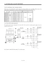
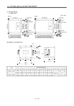
Dimensions [mm (in) ]
Servo amplifier
Model
W W1 H D D1 C
Mounting
screw size
Terminal
screw size
Mass
[kg (lb)]
MR-J2S-10CP(1)/20CP FR-BAL-0.4K
135 (5.31) 120 (4.72) 115 (4.53) 59 (2.32)
45
(1.77
)
7.5 (0.29)
M4
M3.5
2.0 (4.4)
MR-J2S-40CP/20CP1 FR-BAL-0.75K 135 (5.31) 120 (4.72) 115 (4.53) 69 (2.72)
57
(2.24
)
7.5 (0.29)
M4
M3.5
2.8 (6.17)
MR-J2S-60CP/ 70CP/
40CP1
FR-BAL-1.5K
160 (6.30) 145 (5.71) 140 (5.51) 71 (2.79)
55
(2.17
)
7.5 (0.29)
M4
M3.5
3.7 (8.16)
MR-J2S-100CP
FR-BAL-2.2K
160 (6.30) 145 (5.71) 140 (5.51) 91 (3.58)
75
(2.95
)
7.5 (0.29)
M4
M3.5
5.6 (12.35)
MR-J2S-200CP
FR-BAL-3.7K
220 (8.66) 200 (7.87) 192 (7.56) 90 (3.54)
70
(2.76
)
10 (0.39)
M5
M4
8.5 (18.74)
MR-J2S-350CP
FR-BAL-7.5K
220 (8.66) 200 (7.87) 194 (7.64) 120 (4.72)
100
(3.94
)
10 (0.39)
M5
M5
14.5 (32.0)
MR-J2S-500CP FR-BAL-11K
280
(11.02) 255 (10.04) 220 (8.66) 135 (5.31)
100
(3.94
)
12.5 (0.49)
M6 M6
19
(41.9)
MR-J2S-700CP FR-BAL-15K
295
(11.61) 270 (10.62) 275 (10.83) 133 (5.24)
110
(4.33
)
12.5 (0.49)
M6 M6
27
(59.5)
14.2.4 Relays
The following relays should be used with the interfaces.
Interface Selection
example
Relay used for input signals (interface DI-1) signals
To prevent defective contacts , use a relay for small signal
(twin contacts).
(Ex.) Omron : type G2A , MY
Relay used for digital output signals (interface DO-1)
Small relay with 12VDC or 24VDC of 40mA or less
(Ex.) Omron : type MY
14.2.5 Surge absorbers
A surge absorber is required for the electromagnetic brake. Use the following surge absorber or equivalent.
Insulate the wiring as shown in the diagram.
Maximum rating
Permissible circuit
voltage
Surge
immunity
Energy
immunity
Rated
power
Maximum
limit voltage
Static
capacity
(reference
value)
Varistor voltage
rating (range) V1mA
AC[Vma] DC[V]
[A]
[J]
[W] [A] [V]
[pF]
[V]
140 180
(Note)
500/time
5 0.4
25
360
300
220
(198 to 242)
Note. 1 time 8 20 s
(Example) ERZV10D221 (Matsushita Electric Industry)
TNR-10V221K (Nippon chemi-con)
Outline drawing [mm] ( [in] ) (ERZ-C10DK221)
13.5 (0.53)
16
.5
(0
.6
5)
3.
0
(0
.1
2)
or
le
ss
30
.0
(
1.
18
)
or
m
or
e
Crimping terminal
for M4 screw
Vinyl tube
4.7 1.0 (0.19 0.04)
0.8 (0.03)
Summary of Contents for MR-J2S-10CP
Page 11: ...A 10 MEMO ...
Page 19: ...8 MEMO ...
Page 45: ...1 26 1 FUNCTIONS AND CONFIGURATION MEMO ...
Page 181: ...6 20 6 MR Configurator SERVO CONFIGURATION SOFTWARE MEMO ...
Page 207: ...7 26 7 DISPLAY AND OPERATION MEMO ...
Page 219: ...8 12 8 GENERAL GAIN ADJUSTMENT MEMO ...
Page 229: ...9 10 9 SPECIAL ADJUSTMENT FUNCTIONS MEMO ...
Page 231: ...10 2 10 INSPECTION MEMO ...
Page 249: ...12 8 12 OUTLINE DIMENSION DRAWINGS MEMO ...
Page 257: ...13 8 13 CHARACTERISTICS MEMO ...

