5
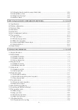
13. CHARACTERISTICS
13- 1 to 13- 8
13.1 Overload protection characteristics................................................................................................... 13- 1
13.2 Power supply equipment capacity and generated loss .................................................................... 13- 2
13.3 Dynamic brake characteristics........................................................................................................... 13- 4
13.3.1 Dynamic brake operation............................................................................................................. 13- 4
13.3.2 The dynamic brake at the load inertia moment........................................................................ 13- 6
13.4 Encoder cable flexing life.................................................................................................................... 13- 6
13.5 Inrush currents at power-on of main circuit and control circuit .................................................... 13- 7
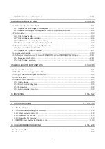
14. OPTIONS AND AUXILIARY EQUIPMENT
14- 1 to 14-50
14.1 Options.................................................................................................................................................. 14- 1
14.1.1 Regenerative options .................................................................................................................... 14- 1
14.1.2 FR-BU2 brake unit....................................................................................................................... 14- 9
14.1.3 Power regeneration converter ....................................................................................................14-15
14.1.4 Cables and connectors.................................................................................................................14-18
14.1.5 Junction terminal block (MR-TB20) ..........................................................................................14-26
14.1.6 Maintenance junction card (MR-J2CN3TM) ............................................................................14-28
14.1.7 External digital display (MR-DP60) ..........................................................................................14-30
14.1.8 Manual pulse generator (MR-HDP01) ......................................................................................14-32
14.1.9 Battery (MR-BAT, A6BAT).........................................................................................................14-33
14.2 Auxiliary equipment ..........................................................................................................................14-34
14.2.1 Recommended wires....................................................................................................................14-34
14.2.2 Circuit breakers, fuses, magnetic contactors............................................................................ 14-36
14.2.3 Power factor improving reactors ................................................................................................14-36
14.2.4 Relays............................................................................................................................................14-37
14.2.5 Surge absorbers ...........................................................................................................................14-37
14.2.6 Noise reduction techniques.........................................................................................................14-38
14.2.7 Leakage current breaker ............................................................................................................14-45
14.2.8 EMC filter.....................................................................................................................................14-47
14.2.9 Setting potentiometers for analog inputs..................................................................................14-50
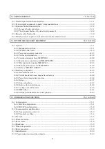
15. COMMUNICATION FUNCTIONS
15- 1 to 15-40
15.1 Configuration ....................................................................................................................................... 15- 1
15.1.1 RS-422 configuration.................................................................................................................... 15- 1
15.1.2 RS-232C configuration ................................................................................................................. 15- 2
15.2 Communication specifications............................................................................................................ 15- 3
15.2.1 Communication overview............................................................................................................. 15- 3
15.2.2 Parameter setting......................................................................................................................... 15- 4
15.3 Protocol ................................................................................................................................................. 15- 5
15.4 Character codes ................................................................................................................................... 15- 7
15.5 Error codes ........................................................................................................................................... 15- 8
15.6 Checksum ............................................................................................................................................. 15- 8
15.7 Time-out operation .............................................................................................................................. 15- 9
15.8 Retry operation .................................................................................................................................... 15- 9
15.9 Initialization........................................................................................................................................15-10
15.10 Communication procedure example ...............................................................................................15-10
Summary of Contents for MR-J2S-10CP
Page 11: ...A 10 MEMO ...
Page 19: ...8 MEMO ...
Page 45: ...1 26 1 FUNCTIONS AND CONFIGURATION MEMO ...
Page 181: ...6 20 6 MR Configurator SERVO CONFIGURATION SOFTWARE MEMO ...
Page 207: ...7 26 7 DISPLAY AND OPERATION MEMO ...
Page 219: ...8 12 8 GENERAL GAIN ADJUSTMENT MEMO ...
Page 229: ...9 10 9 SPECIAL ADJUSTMENT FUNCTIONS MEMO ...
Page 231: ...10 2 10 INSPECTION MEMO ...
Page 249: ...12 8 12 OUTLINE DIMENSION DRAWINGS MEMO ...
Page 257: ...13 8 13 CHARACTERISTICS MEMO ...

