175
activates the KEB function.
<1> When P2-05=0, the drive accelerates to the previously active frequency according to the active acceleration
time set by any of C1-00, C1-02, C1-04 or C1-06. When P2-05≠0, the drive accelerates using the acceleration time
set to P2-05.
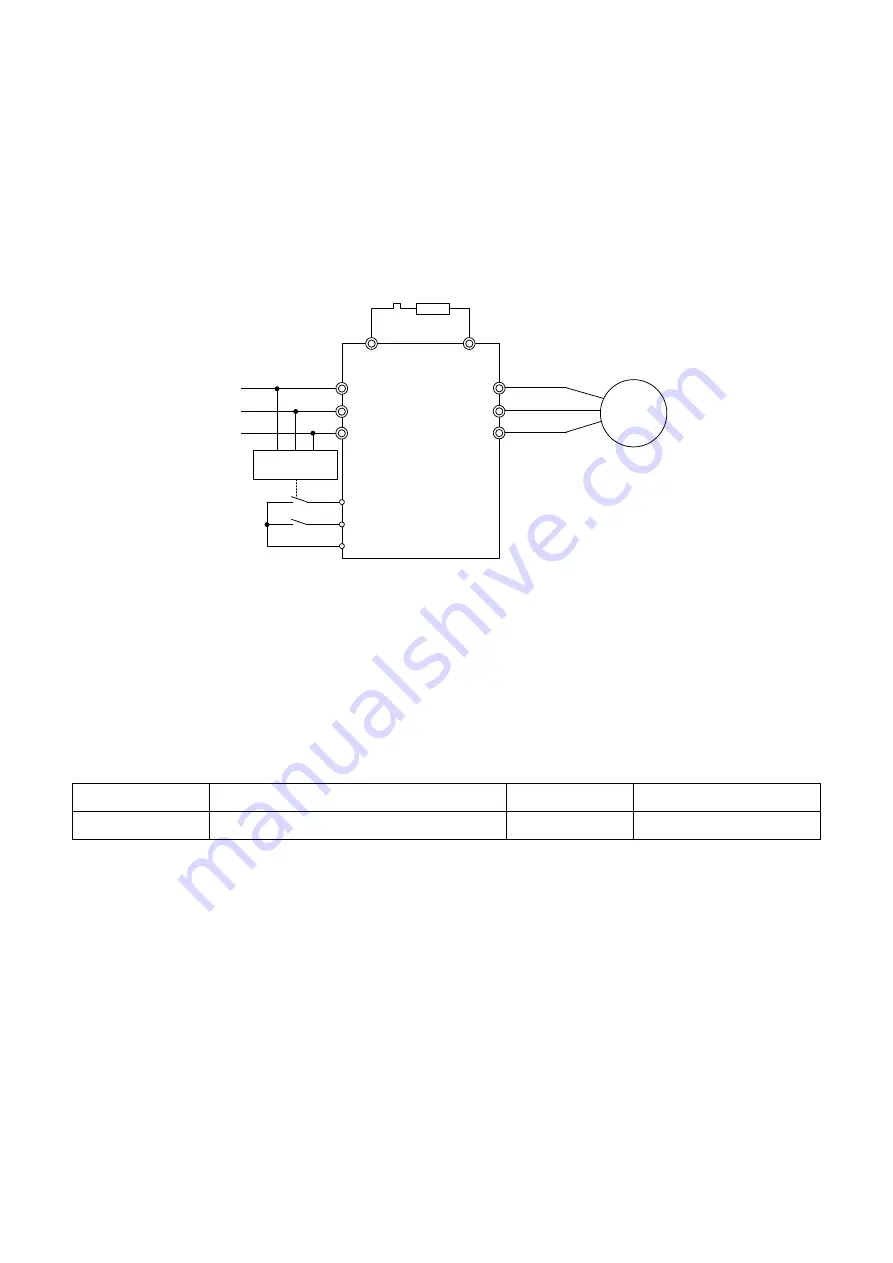
Figure 6.77 illustrates a wiring example to trigger KEB at the momentary power loss using terminal S6.
Drive
M
Uv detection
relay
Braking resistor
(option)
B
1
B
2
R/L1
S/L2
T/L3
U/T1
V/T2
W/T3
L1
L2
L3
S6 (KEB Command 1 / 2)
S1 Run command
SC
Figure 6.77 KEB Function Wiring
Note:
1.
Check if a Run command during power loss is enabled. When the Run command is removed, the drive cannot
accelerate to the frequency command even if the power is restored.
2. Install a braking resistor option when P2-09 = 1 ( KEB Operation Method 2).
P2-10
Automatic voltage regulation
No.
Name
Setting Range
Default
P2-10
Automatic voltage regulation
0, 1
1
0 : Disabled
1 : Enabled
P3 Stall Prevention
When the load is too heavy or the deceleration time is too short, the motor may not be able to
keep up with the frequency command and slips. The regenerative power from the power will
then exceed the tolerance of main circuit capacitor and trigger an ov (Overvoltage) fault to
stop the drive. This process is called “stall”. When a motor stalls, it cannot be accelerated or
decelerated. The Stall Prevention Function prevents the motor from stalling and while allowing
the motor to keep up with the desired speed without changing the acceleration or
Summary of Contents for EVO 6800 Series
Page 1: ...MANUAL Compact Vector Drive EVO 6800 Series...
Page 33: ...33 34 2 36 0 2 8 93 0...
Page 35: ...35 4 2 Main Circuit...
Page 41: ...41 4 3 Control Circuit...


