234
Time
set to 0)
If the drive does not receive any response via pulse train communication within the time set in
E6-09, the fault will be triggered to perform the action set in E6-00
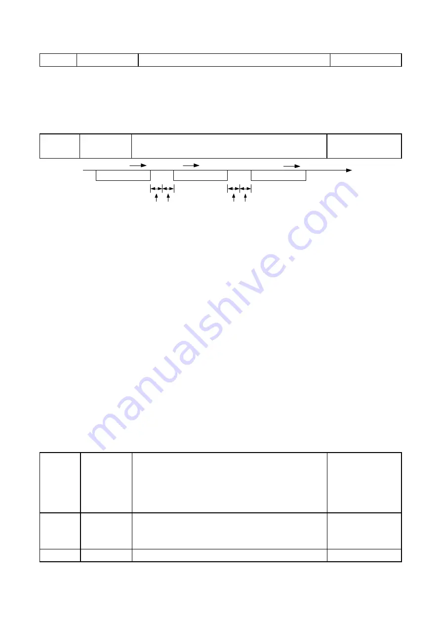
E6- 10
Transmit Wait Time
Sets the wait time between sending and receiving data.
E6-10
Transmit
Wait Time
Sets the wait time between sending and receiving
data.
Default: 5ms
Range: 5 to 65 ms
PLC/Controller Drive
Command Data
Drive PLC/Controller
Command Data
Response Message
24 bits
E6-10
24 bits
5ms Min.
PLC/Controller Drive
11.4 Drive Operations by Modbus
The drive operations by Modbus communication are determined by the drive parameter
settings. This section explains the provided functions and the related parameters.
11.4.1 Actions by Modbus
The following actions can be performed by a PLC regardless of the parameter settings except
for E6 parameters.
·
Monitor drive operation from a PLC.
·
View and change parameter settings.
·
Reset faults.
·
Assign fulti-function inputs.
11.4.2 Drive Control by Modbus
Select Modbus communication according to the following table to run/stop the motor and
give frequency commands.
b1-00
Frequency
Command
Selection 1
0
∶
Keypad
1
∶
Control Circuit Terminal (Analog Input)
2
∶
Terminal Up/Down
3
∶
Modbus Communication
4
∶
Pulse Train Input (Including PWM signal input)
Default
∶
1
Min.: 0
Max.: 4
b1-01
Run
Command
Selection 1
0
∶
Keypad
1
∶
Control Circuit Terminal (Sequence Control Input)
2
∶
Modbus Communication
Default
∶
1
Range: 0, 1, 2
b1-07 Frequency
Enabled while E1-00 to E1-07 is set to 4 and the DIP
Default
∶
0
Summary of Contents for EVO 6800 Series
Page 1: ...MANUAL Compact Vector Drive EVO 6800 Series...
Page 33: ...33 34 2 36 0 2 8 93 0...
Page 35: ...35 4 2 Main Circuit...
Page 41: ...41 4 3 Control Circuit...


