00
00
00
00
00
00
0
0
0
0
0
0
0
0
00
00
00
00
00
00
000000
000000
000000
000000
000000
000000
00
00
00
00
00
00
0
0
0
00
00
00
00
00
00
0
0
0
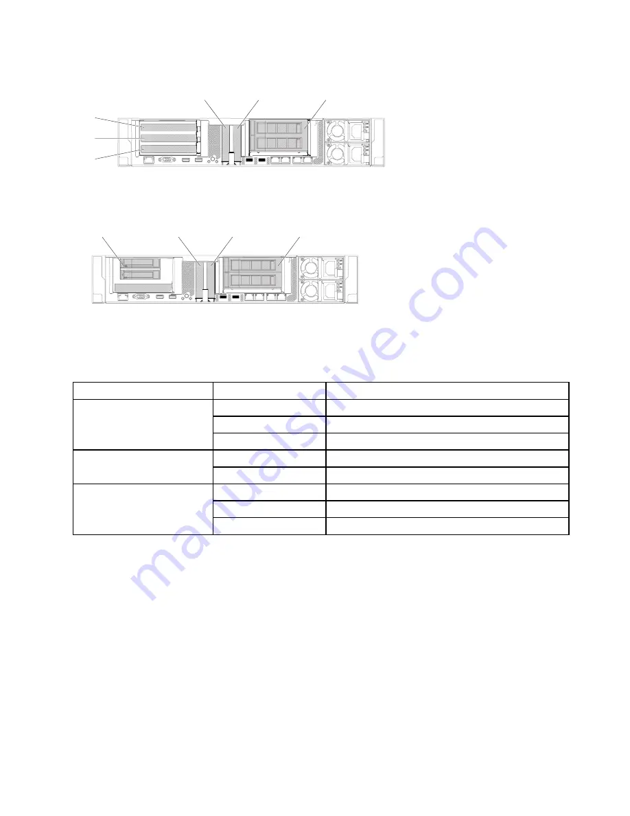
Slot 1
Slot 2
Slot 3
Slot 4
Slot 5
3.5-inch rear two
hard-disk-drive kit
0000000
0000000
000000
000000
000000
000000
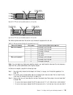
Figure 125. PCI riser-card adapter expansion slot locations
00
00
00
00
00
00
0
0
0
0
0
0
0
0
0
0
00
00
00
00
00
00
00
00
00
00
00
00
00
00
00
00
00
00
00
00
00
00
00
00
000
000
0
0
000
000
0
0
0000000
0000000
000000
000000
000000
000000
000000
000000
Slot 4
Slot 5
3.5-inch rear two
hard-disk-drive kit
2.5-inch rear two
hard-disk-drive kit
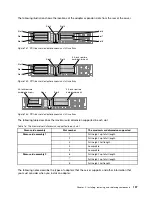
Figure 126. PCI riser-card adapter expansion slot locations
The following table describes the maximal card dimension supported in each slot.
Table 15. The maximal card dimension supported in each slot
Riser-card assembly
Slot number
The maximal card dimension supported
1
Full height, up to full length
2
Full height, up to full length
Riser-card assembly 1
3
Full height, half length
4
Low-profile
5
Low-profile
6
Full height, up to full length
7
Full height, up to full length
Riser-card assembly 2
8
Full height, half length
Note:
If you are replacing a high power graphics adapter, you might need to disconnect the internal power
cable from the system board before removing the adapter.
To remove an adapter, complete the following steps:
Step 1.
Read the safety information that begins on “Safety” on page v and “Installation guidelines” on
page 297.
Step 2.
Turn off the server and peripheral devices and disconnect all power cords; then, remove the top
cover (see “Removing the top cover” on page 149).
Step 3.
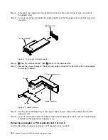
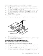
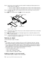
Remove the riser-card assembly that contains the adapter (see “Removing a riser-card assembly”
on page 186).
• If you are removing an adapter from PCI expansion slot 1, 2, or 3, remove riser-card assembly 1.
• If you are removing an adapter from PCI expansion slot 6, 7 or 8, remove riser-card assembly 2.
Installing, removing, and replacing components
193
Summary of Contents for x3650 M5
Page 1: ...Lenovo System x3650 M5 Installation and Service Guide Machine Type 8871 ...
Page 47: ...Figure 35 System board switches jumpers and buttons Chapter 1 The System x3650 M5 server 35 ...
Page 60: ...48 Lenovo System x3650 M5 Installation and Service Guide ...
Page 80: ...68 Lenovo System x3650 M5 Installation and Service Guide ...
Page 124: ...112 Lenovo System x3650 M5 Installation and Service Guide ...
Page 146: ...134 Lenovo System x3650 M5 Installation and Service Guide ...
Page 1322: ...1310 Lenovo System x3650 M5 Installation and Service Guide ...
Page 1330: ...Taiwan BSMI RoHS declaration 1318 Lenovo System x3650 M5 Installation and Service Guide ...
Page 1339: ......
Page 1340: ......

