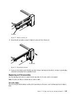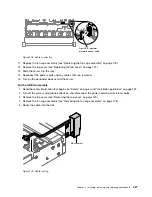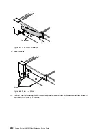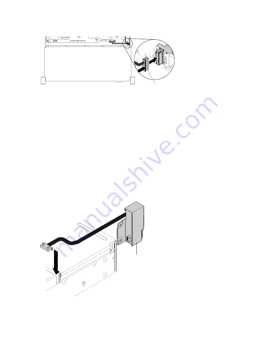
Front USB / operator
information panel cable
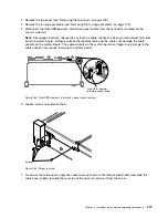
Figure 189. Cable connection
11. Replace the fan cage assembly (see “Replacing the fan cage assembly” on page 179).
12. Replace the top cover (see “Replacing the top cover” on page 151).
13. Slide the server into the rack.
14. Reconnect the power cords and any cables that you removed.
15. Turn on the peripheral devices and the server.
For the left EIA assembly
1. Read the safety information that begins on “Safety” on page v and “Installation guidelines” on page 297.
2. Turn off the server and peripheral devices, and disconnect the power cord and all external cables.
3. Remove the top cover (see “Removing the top cover” on page 149).
4. Remove the fan cage assembly (see “Removing the fan cage assembly” on page 178).
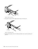
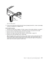
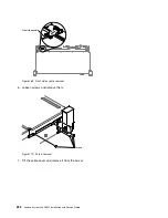
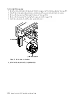
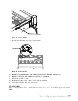
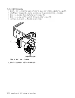
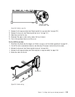
5. Route the cable into the slot.
EIA assembly
Figure 190. Cable routing
Installing, removing, and replacing components
233
Summary of Contents for x3650 M5
Page 1: ...Lenovo System x3650 M5 Installation and Service Guide Machine Type 8871 ...
Page 47: ...Figure 35 System board switches jumpers and buttons Chapter 1 The System x3650 M5 server 35 ...
Page 60: ...48 Lenovo System x3650 M5 Installation and Service Guide ...
Page 80: ...68 Lenovo System x3650 M5 Installation and Service Guide ...
Page 124: ...112 Lenovo System x3650 M5 Installation and Service Guide ...
Page 146: ...134 Lenovo System x3650 M5 Installation and Service Guide ...
Page 1322: ...1310 Lenovo System x3650 M5 Installation and Service Guide ...
Page 1330: ...Taiwan BSMI RoHS declaration 1318 Lenovo System x3650 M5 Installation and Service Guide ...
Page 1339: ......
Page 1340: ......

