• The maximum memory speed is determined by the combination of the microprocessor, DIMM speed,
DIMM type, Operating Modes in UEFI settings, and the number of DIMMs installed in each channel.
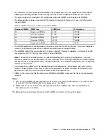
• The server supports a maximum of 24 single-rank, dual-rank RDIMMs or 24 quad-rank LRIMMs.
• The following table shows an example of the maximum amount of memory that you can install using
ranked DIMMs:
Table 11. Maximum memory installation using ranked DIMMs
Number of DIMMs
DIMM type
DIMM size
Total memory
24
Single-rank RDIMMs
8 GB
192 GB
24
Dual-rank RDIMMs
8 GB
192 GB
24
Dual-rank RDIMMs
16 GB
384 GB
24
Dual-rank RDIMMs
32 GB
768 GB
24
Quad-rank LRDIMMs
64 GB
1.5 TB
• The RDIMM options that are available for the server are 8 GB, 16 GB, and 32 GB. The server supports a
minimum of 8 GB and a maximum of 768 GB of system memory using RDIMMs.
• The LRDIMM option that is available for the server is 64 GB. The server supports a minimum of 64 GB
and a maximum of 1.5 TB of system memory using LRDIMMs.
Note:
The amount of usable memory is reduced depending on the system configuration. A certain
amount of memory must be reserved for system resources. To view the total amount of installed memory
and the amount of configured memory, run the Setup Utility. For additional information, see “Configuring
the server” on page 50.
• A minimum of one DIMM must be installed for each microprocessor. For example, you must install a
minimum of two DIMMs if the server has two microprocessors installed. However, to improve system
performance, install a minimum of four DIMMs for each microprocessor.
• DIMMs in the server must be the same type (RDIMM or LRDIMM) to ensure that the server will operate
correctly.
Notes:
1. You can install DIMMs for microprocessor 2 as soon as you install microprocessor 2; you do not have
to wait until all of the DIMM slots for microprocessor 1 are filled.
2. DIMM slots 13-24 are reserved for microprocessor 2; thus, DIMM slots 13-24 are enabled when
microprocessor 2 is installed.
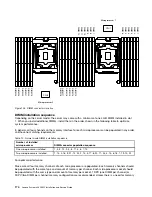
The following illustration shows the location of the DIMM connectors on the system board.
Installing, removing, and replacing components
173
Summary of Contents for x3650 M5
Page 1: ...Lenovo System x3650 M5 Installation and Service Guide Machine Type 8871 ...
Page 47: ...Figure 35 System board switches jumpers and buttons Chapter 1 The System x3650 M5 server 35 ...
Page 60: ...48 Lenovo System x3650 M5 Installation and Service Guide ...
Page 80: ...68 Lenovo System x3650 M5 Installation and Service Guide ...
Page 124: ...112 Lenovo System x3650 M5 Installation and Service Guide ...
Page 146: ...134 Lenovo System x3650 M5 Installation and Service Guide ...
Page 1322: ...1310 Lenovo System x3650 M5 Installation and Service Guide ...
Page 1330: ...Taiwan BSMI RoHS declaration 1318 Lenovo System x3650 M5 Installation and Service Guide ...
Page 1339: ......
Page 1340: ......

