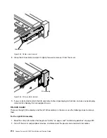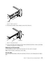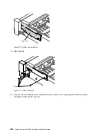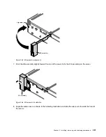
EIA assembly
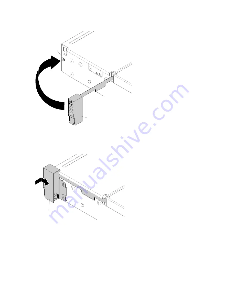
Alignment pin
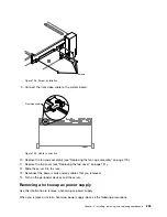
Figure 185. EIA assembly alignment
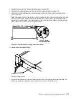
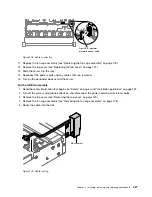
7. Push the EIA assembly slightly toward the rear of the server to fix the EIA assembly on the server.
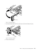
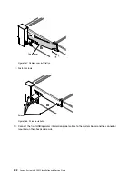
EIA assembly
Figure 186. EIA assembly installation
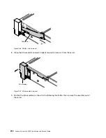
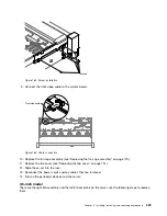
8. Angle the cable cover as shown in the following illustration and slide the cable arm towards the front of
the server.
Installing, removing, and replacing components
231
Summary of Contents for x3650 M5
Page 1: ...Lenovo System x3650 M5 Installation and Service Guide Machine Type 8871 ...
Page 47: ...Figure 35 System board switches jumpers and buttons Chapter 1 The System x3650 M5 server 35 ...
Page 60: ...48 Lenovo System x3650 M5 Installation and Service Guide ...
Page 80: ...68 Lenovo System x3650 M5 Installation and Service Guide ...
Page 124: ...112 Lenovo System x3650 M5 Installation and Service Guide ...
Page 146: ...134 Lenovo System x3650 M5 Installation and Service Guide ...
Page 1322: ...1310 Lenovo System x3650 M5 Installation and Service Guide ...
Page 1330: ...Taiwan BSMI RoHS declaration 1318 Lenovo System x3650 M5 Installation and Service Guide ...
Page 1339: ......
Page 1340: ......


