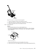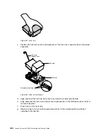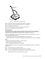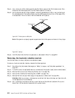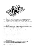
Step 12. Remove the memory modules and set them aside on a static-protective surface for reinstallation
(see “Removing a memory module” on page 171).
Note:
Make a note of the location of each DIMM as you remove it, so that you can later reinstall it
in the same connector.
Step 13. (Trained technician only) Remove all heat sinks and microprocessors, and set them aside on
a static-protective surface for reinstallation (see “Removing a microprocessor and heat sink” on
page 276).
Note:
Do not allow the thermal grease to come in contact with anything, and keep each heat sink
paired with its microprocessor for reinstallation. Contact with any surface can compromise the
thermal grease and the microprocessor socket. A mismatch between the microprocessor and its
original heat sink can require the installation of a new heat sink.
Step 14. Disconnect all cables from the system board. Make a list of each cable as you disconnect it; you
can then use this as a checklist when you install the new system board (see “Internal cable routing
and connectors” on page 135 for more information).
Attention:
Disengage all latches, release tabs or locks on cable connectors when you disconnect
all cables from the system board. Failing to release them before removing the cables will damage
the cable sockets on the system board. The cable sockets on the system board are fragile. Any
damage to the cable sockets may require replacing the system board.
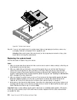
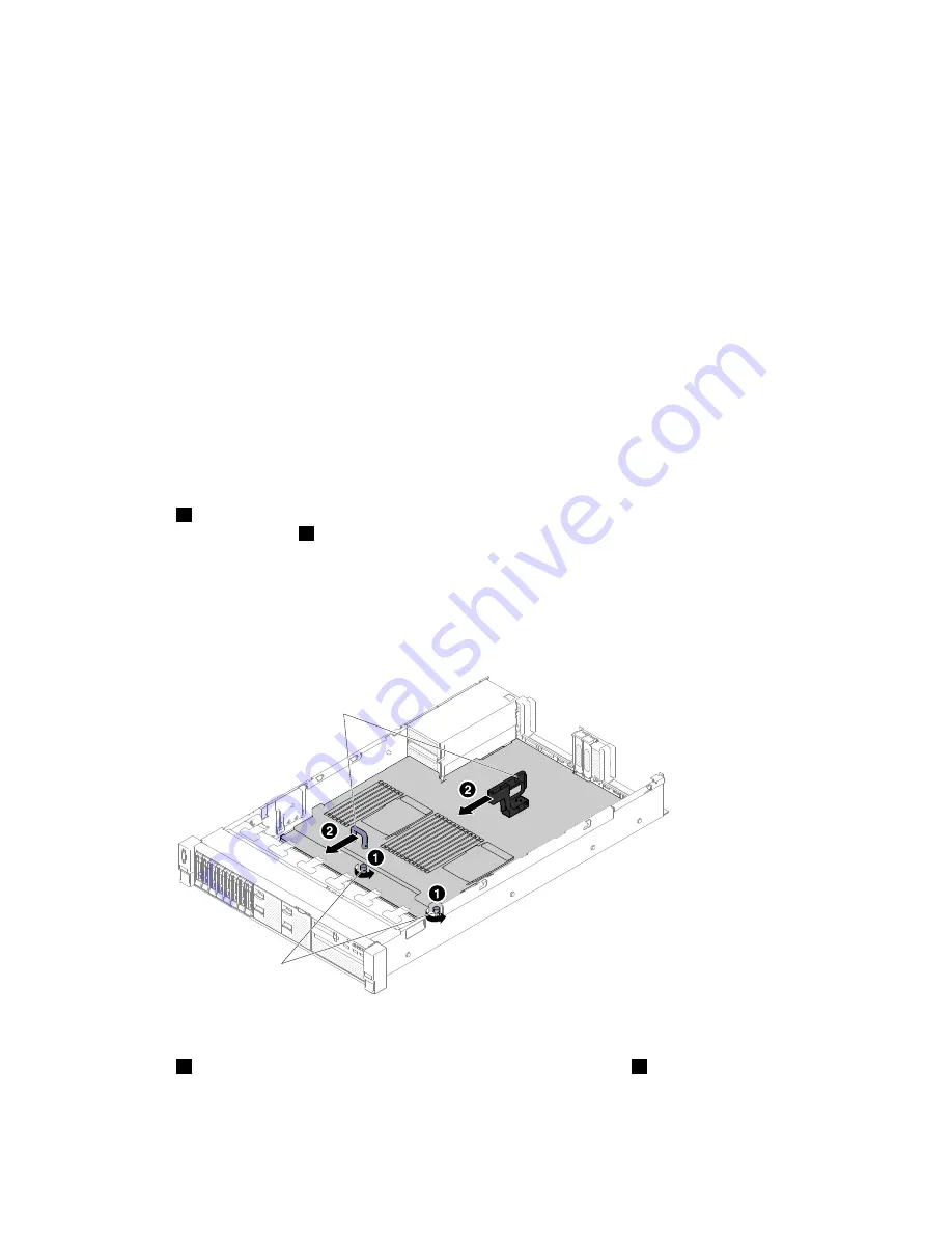
Step 15.
1
Loosen the two thumbscrews (located near the front of the server) that secure the system board
to the server and
2
slide the system board toward the front of the server.
Step 16. Grasp both system-board handles and lift up the left side of the system board slightly and carefully
remove it from the chassis, being careful not to damage any surrounding components.
Note:
Use the system-board handles to lift the system board only. Do not attempt to lift the
server using the system board handles.
00
00
00
00
0
0
0
0
000
000
000
000
000
000
0
0
0
00
00
00
00
00
00
00
00
00
00
00
00
00
00000
00000
00000
00000
Thumb screws
System board handles
Figure 266. System board removal
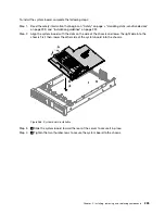
Step 17.
1
Push the system board toward the broadside of the server and
2
lift the system board up.
Installing, removing, and replacing components
293
Summary of Contents for x3650 M5
Page 1: ...Lenovo System x3650 M5 Installation and Service Guide Machine Type 8871 ...
Page 47: ...Figure 35 System board switches jumpers and buttons Chapter 1 The System x3650 M5 server 35 ...
Page 60: ...48 Lenovo System x3650 M5 Installation and Service Guide ...
Page 80: ...68 Lenovo System x3650 M5 Installation and Service Guide ...
Page 124: ...112 Lenovo System x3650 M5 Installation and Service Guide ...
Page 146: ...134 Lenovo System x3650 M5 Installation and Service Guide ...
Page 1322: ...1310 Lenovo System x3650 M5 Installation and Service Guide ...
Page 1330: ...Taiwan BSMI RoHS declaration 1318 Lenovo System x3650 M5 Installation and Service Guide ...
Page 1339: ......
Page 1340: ......

