H
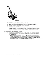
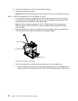
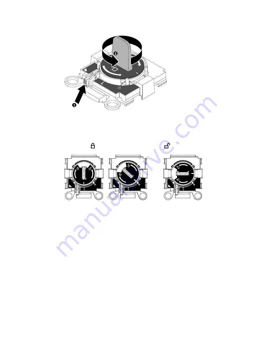
Figure 244. Installation tool handle adjustment
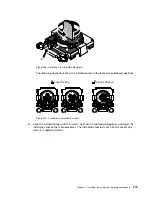
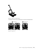
The following illustrations show the installation tool in the locked and unlocked positions.
E
5-
x6
xx
v
3
E
5-
x6
xx
v
4
E
5
-x
6
x
x
v
3
E
5
-x
6
x
x
v
4
E5-x6xx v3
E5-x6xx v4
Lock Position
Unlock Position
Figure 245. Locked and unlocked positions
b.
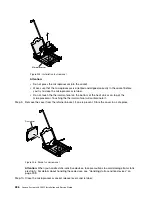
Align the installation tool with the screws, as shown in the following graphic, and lower the
installation tool on the microprocessor. The installation tool rests flush on the socket only
when it is aligned correctly.
Installing, removing, and replacing components
279
Summary of Contents for x3650 M5
Page 1: ...Lenovo System x3650 M5 Installation and Service Guide Machine Type 8871 ...
Page 47: ...Figure 35 System board switches jumpers and buttons Chapter 1 The System x3650 M5 server 35 ...
Page 60: ...48 Lenovo System x3650 M5 Installation and Service Guide ...
Page 80: ...68 Lenovo System x3650 M5 Installation and Service Guide ...
Page 124: ...112 Lenovo System x3650 M5 Installation and Service Guide ...
Page 146: ...134 Lenovo System x3650 M5 Installation and Service Guide ...
Page 1322: ...1310 Lenovo System x3650 M5 Installation and Service Guide ...
Page 1330: ...Taiwan BSMI RoHS declaration 1318 Lenovo System x3650 M5 Installation and Service Guide ...
Page 1339: ......
Page 1340: ......

