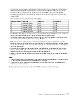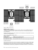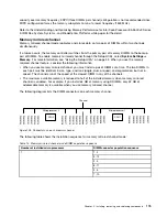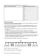
• Install at least two single-rank or dual-rank DIMMs in a channel.
Table 14. Memory rank sparing mode DIMM population sequence
Number of DIMMs
Number of installed
microprocessor
DIMM connector
First pair of DIMMs
1
1, 2
Second pair of DIMMs
1
4, 5
Third pair of DIMMs
1
8, 9
Fourth pair of DIMMs
1
11, 12
Fifth pair of DIMMs
1
3, 6
Sixth pair of DIMMs
1
7, 10
Seventh pair of DIMMs
1
13, 14
Eighth pair of DIMMs
1
16, 17
Ninth pair of DIMMs
1
20, 21
Tenth pair of DIMMs
1
23, 24
Eleventh pair of DIMMs
1
15, 18
Twelfth pair of DIMMs
1
19, 22
Replacing a memory module
Use this information to replace a memory module.
Step 1.
Read the safety information that begins on “Safety” on page v and “Installation guidelines” on
page 297.
Step 2.
Turn off the server and peripheral devices and disconnect the power cords and all external cables,
if necessary.
Step 3.
Remove the top cover (see “Removing the top cover” on page 149).
Step 4.
Remove the air baffle (see “Removing the air baffle” on page 152).
Step 5.
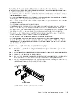
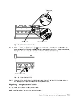
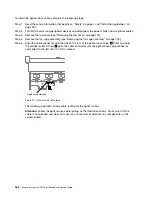
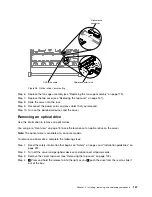
Carefully open the retaining clips on each end of the DIMM connector and remove the DIMM.
Attention:
To avoid breaking the retaining clips or damaging the DIMM connectors, open and
close the clips gently.
Installing, removing, and replacing components
177
Summary of Contents for x3650 M5
Page 1: ...Lenovo System x3650 M5 Installation and Service Guide Machine Type 8871 ...
Page 47: ...Figure 35 System board switches jumpers and buttons Chapter 1 The System x3650 M5 server 35 ...
Page 60: ...48 Lenovo System x3650 M5 Installation and Service Guide ...
Page 80: ...68 Lenovo System x3650 M5 Installation and Service Guide ...
Page 124: ...112 Lenovo System x3650 M5 Installation and Service Guide ...
Page 146: ...134 Lenovo System x3650 M5 Installation and Service Guide ...
Page 1322: ...1310 Lenovo System x3650 M5 Installation and Service Guide ...
Page 1330: ...Taiwan BSMI RoHS declaration 1318 Lenovo System x3650 M5 Installation and Service Guide ...
Page 1339: ......
Page 1340: ......

