Step 4.
Reinstall any adapters and reconnect any internal cables you might have removed in other
procedures (see “Replacing an adapter” on page 196 and “Internal cable routing and connectors”
on page 135).
Step 5.
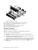
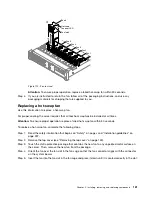
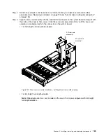
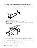
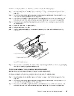
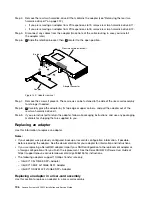
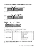
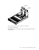
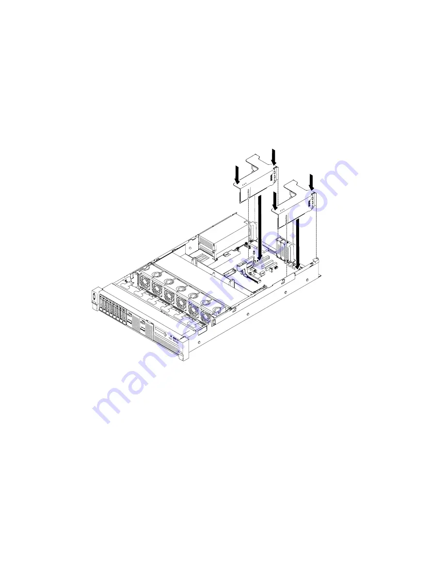
Align the riser-card assembly with the selected PCI connector on the system board and align it with
the slots on the chassis; then, lower it into the server and press down firmly until the riser-card
assembly is seated correctly in the connector on the system board.
• For half-length and low profile adapters
0
0
0
0
0
0
0
0
0
000
000
000
000
000
000
000
000
0
0
0
0
0
0
0
00
00
00
00
00
00
00
00
00
00
00000
00000
00000
00000
PCI riser-card
assembly 2
PCI riser-card
assembly 1
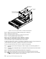
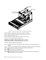
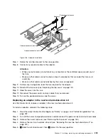
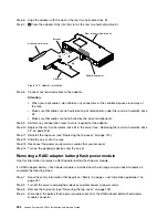
Figure 120. Riser-card assembly installation - half-length and low profile adapters
• For full-height, full-length adapters
Note:
Shipping brackets are only included in the server that is pre-configured with full-height,
full-length adapters
Installing, removing, and replacing components
189
Summary of Contents for x3650 M5
Page 1: ...Lenovo System x3650 M5 Installation and Service Guide Machine Type 8871 ...
Page 47: ...Figure 35 System board switches jumpers and buttons Chapter 1 The System x3650 M5 server 35 ...
Page 60: ...48 Lenovo System x3650 M5 Installation and Service Guide ...
Page 80: ...68 Lenovo System x3650 M5 Installation and Service Guide ...
Page 124: ...112 Lenovo System x3650 M5 Installation and Service Guide ...
Page 146: ...134 Lenovo System x3650 M5 Installation and Service Guide ...
Page 1322: ...1310 Lenovo System x3650 M5 Installation and Service Guide ...
Page 1330: ...Taiwan BSMI RoHS declaration 1318 Lenovo System x3650 M5 Installation and Service Guide ...
Page 1339: ......
Page 1340: ......

