GE M
EDICAL
S
YSTEMS
D
IRECTION
FK091075, R
EVISION
04
V
IVID
3N P
RO
/E
XPERT
S
ERVICE
M
ANUAL
8-98
Section 8-6 - Lower Section Components Replacement
8-6-5-3
Gas Spring Cable Installation Procedure
1) Raise the control console to its
maximum
height.
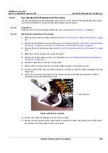
2) Route the gas spring cable along its original path in the machine. The end of the cable with the
adjustable sleeve should be next to the release handle underneath the keyboard; the other end of
the cable should be next to the lower end of the gas spring.
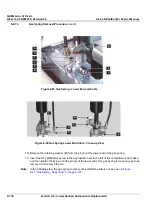
3) Fit the cable end stopper on the trigger arm.
4) Fit the groove of the cable end sleeve on the hinge of the gas spring head.
5) Turn the cable holder over the cable end sleeve, and then fasten it with the securing screw.
6) Insert the other cable end stopper into the release handle located underneath the keyboard, and
then insert the wire into the slot and screw in the cable adjustment sleeve.
7) Adjust the securing nut so that there is no backlash of the release handle, and secure the
adjustment with the nut.
8) Using the release handle, lower and raise the control console several times to verify its proper
operation.
9) Fasten the cables to the machine with cable ties (at the original positions).
10) Return the front end crate to its original position, as described in
8-4-5-4 "Front End Crate
Installation Procedure" on page 8-52
.
11) Replace the Vivid 3N rear, left and right covers, as described in
8-2-4-4 "Rear Cover Installation
Procedure" on page 8-7
and
8-2-2-4 "Side Covers Installation Procedure" on page 8-4
.
12) Raise the control console to its
maximum
height, and then replace the bottom keyboard cover, as
described in
8-2-8-4 "Bottom Keyboard Cover Installation Procedure" on page 8-15
.
13) Insert the air filter in its original location, as shown in
Figure 8-3 "Air Filter" on page 8-5
.
Note:
It is recommended to clean the filter before returning it to its original location, as described
in
Chapter 10 -
.
14) Verify that the gas spring release handle is functioning correctly.

