GE M
EDICAL
S
YSTEMS
D
IRECTION
FK091075, R
EVISION
04
V
IVID
3N P
RO
/E
XPERT
S
ERVICE
M
ANUAL
8-134
Section 8-8 - Peripherals
8-8-4
Sony UP 2950 MD & 2800P Color Video Printer Replacement Procedure
NOTE:
This section describes the installation and removal procedures of the Sony UP-2800P and UP/2950MD
Color Video Printers.
The Sony UP-2950MD Color Video Printer has a NTSC/PAL Selector on the rear panel while the Sony
UP-2800P Color Video Printer is PAL only.
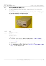
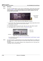
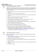
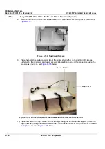
Figure 8-116 SONY Color Video Printer
In this section, two types of replacement procedures are described, as follows:
•
For units that are equipped with a previously-installed B/W printer and/or VCR
(see
8-8-4-4 "Color Video Printer Installation - Procedure1" on page 8-135
, and
8-8-4-5 "Color
Video Printer Removal - Procedure 1" on page 8-139
).
•
For units that are not equipped with a previously-installed B/W printer and/or VCR
(refer to
8-8-4-6 "Color Video Printer Installation - Procedure 2" on page 8-140
, and
8-8-4-7 "Color
Video Printer Removal - Procedure 2" on page 8-140
).
8-8-4-1
Tools
Use the appropriate flat and Phillips-type screw drivers.
8-8-4-2
Manpower
One person - 30 mins.
8-8-4-3
Preparations
1) Shut down the Vivid 3N Pro/Expert ultrasound unit, as described in
Chapter 3 -
Installation
.
2.) Remove the Connectors Panels Cover as described in
8-2-5-3 "Connector Panels Cover Removal
Procedure" on page 8-8
.
3.) Unpack the Color Video Printer.
4.) Check that the Color Video Printer AC voltage corresponds to that of your local voltage.
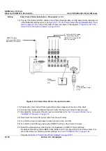
5.) Set the NTSC/PAL selector switch to NTSC (this applies only to Model UP-2950MD) as shown in
Figure 8-122 "Color Video Printer Connection Cables" on page 8-138
.
6.) Install the Color Video Printer accessories, as described in Operating Instructions supplied with the
printer.


