GE M
EDICAL
S
YSTEMS
D
IRECTION
FK091075, R
EVISION
04
V
IVID
3N P
RO
/E
XPERT
S
ERVICE
M
ANUAL
7-54
Section 7-3 - Performing Front End (FE) Diagnostics
7-3-9-1 Accessing the MUX Diagnostic Test Options
(cont’d)
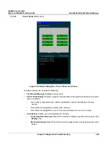
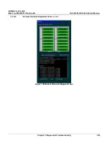
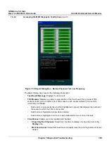
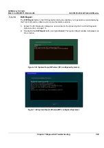
The
Report
dialog box contains the following information:
•
Test Result Message:
Displays the test result.
•
TR4 Modules:
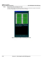
Displays a graphic representation of the front board (four groups of TR4
sockets). Each group consists of four TR4 sockets, each socket containing four vectors
(channels), as follows:
•
Each vector is represented by a button (highlighted in green) that displays the number of
the socket to which the TR4 is connected.
•
Each button is highlighted yellow when selected.
•
Each button is highlighted red if errors were detected for one or more channels.
•
Checkboxes:
Enable you to manipulate bad channels:
•
Show Only Bad Channels:
Select this checkbox to display only bad channels in the
Display
area.
•
Mark bad channel:
Select this checkbox to manually mark the currently selected channel
as bad.
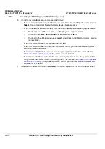
4) Check the test result message and proceed as follows:
•
If one or more channels were identified as bad, trackball to the
Save Report
button and press
Select
, then contact a GE Medical Systems Service Representative.
•
If no channels were identified as bad, mark the channels suspected as being bad as follows:
•
Trackball to each of the channels in the
Display
area and press
Select
.
•
Trackball to the
Mark bad channel
checkbox and press
Select
.
•
Trackball to
Save Report
and press
Select
, and contact a GE Medical Systems service
representative.
5) Trackball to the
Low Freq Test
button and press
Select
. The normal channels diagnostic test is
performed in low frequency mode, and the test results are displayed in the
Report
dialog box, as
shown in
Figure 7-30 "Report Dialog Box - Normal Channels Test Low Frequency" on page 7-55
:

