GE M
EDICAL
S
YSTEMS
D
IRECTION
FK091075, R
EVISION
04
V
IVID
3N P
RO
/E
XPERT
S
ERVICE
M
ANUAL
Chapter 8 Replacement Procedures
8-137
8-8-4-4 Color Video Printer Installation - Procedure1
(cont’d)
14) Lock the belt buckles to tighten the shelf to the top surface. Verify that the B/W printer and VCR are
secure.
15.)Re-connect the previously-disconnected B/W Printer and VCR cables.
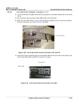
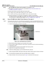
16) Place the Color Video Printer on top of the shelf, allowing sufficient room to access the cables at
the rear of the printer, as shown in
Figure 8-120
below.
Figure 8-120 Color Video Printer and Shelf Installed on the Vivid 3N
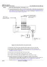
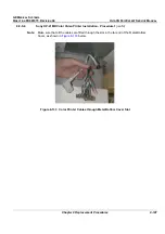
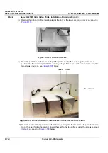
17.)Connect the Ground cable (hanging out of the Bottom Metal Cover) to the Ground screw at the rear
of the Color Video Printer, as shown in
Figure 8-121
below
Figure 8-121 Color Video Printer Ground Cable Connection
Color Video Printer
Ground Cable
Ground Screw


