GE M
EDICAL
S
YSTEMS
D
IRECTION
FK091075, R
EVISION
04
V
IVID
3N P
RO
/E
XPERT
S
ERVICE
M
ANUAL
6-6
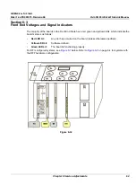
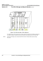
Section 6-3 - Front End Voltages and Signal Indicators
6-3-2
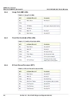
Image Port (IMP) LEDs
6-3-3
Front End Controller (FEC) LEDs
6-3-4
RF and Tissue Processor (RFT)
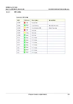
Table 6-4 Image Port LEDs
LED
Indicates When Lit
Comments
Red
Board Failure
Normally ON
Yellow
Yellow
VME Master
Lit during scanning and data transfer
Yellow
VME Slave
Green
Board OK
Normally lit
Red
Board Failure
Normally OFF
Table 6-5 Front End Controller LEDs
LED
Indicates When Lit
Comments
Red
Board Failure
Normally OFF
Green
Board OK
Normally lit
Yellow
Scan
Lit during scanning
Yellow
Probe Change
Lit during probe change
Yellow
No Probe
Lit if no probe is selected
Yellow
HV Over Range
Lit if excessive HV is output,
possibly due to HV surveillance
Table 6-6 RF and Tissue Processor LEDs
LED
Indicates When Lit
Comments
Red
Board Failure
Normally OFF
Green
Board OK
Normally lit
Yellow
DSP Runs
Normally blinking
Yellow
Data Out on Pipeline
Lit during data transfer to pipelink
Red
Clock Problems
Normally OFF
Red
Clock Problems
Normally OFF
Red
Clock Problems
Normally OFF

