GE M
EDICAL
S
YSTEMS
D
IRECTION
FK091075, R
EVISION
04
V
IVID
3N P
RO
/E
XPERT
S
ERVICE
M
ANUAL
7-18
Section 7-3 - Performing Front End (FE) Diagnostics
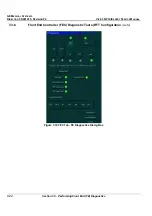
7-3-5 RFT Diagnostic Tests (RFT Configuration)
(cont’d)
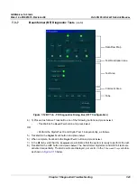
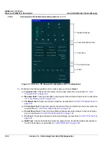
3) In the
RFT
tab, verify that the
Comment
area indicates that the system is ready to perform the test.
4) Trackball to one of the following buttons and press
Select
:
•
Select the
Board Test
button to perform
Self Test 1
and
Self Test 2
sequentially.
•
Select the
Self Test 1
button to perform
Self Test 1
independently.
•
Select the
Self Test 2
button to perform
Self Test 2
independently.
The relevant LED changes color as follows:
•
Yellow:
The test is in progress.
•
Green:
The test has been completed and no problems were identified.
•
Red:
Problems were identified during the performance of the test.
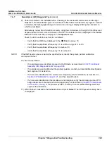
5) Review the test results in the
Comment
area and proceed as follows:
•
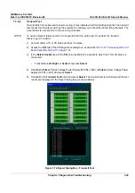
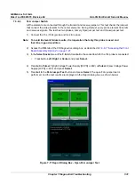
If no problems were identified, proceed to the FEC test, as described in
7-3-6 "Front End
Controller (FEC) Diagnostic Tests (RFT Configuration" on page 7-19
.
•
If no problems were identified but the problem persists, contact your local GE Medical Systems
field engineer for assistance.
•
If errors were identified but the results were marginal, perform calibration, as described in
Section 6-8 "Calibration" on page 6-21
, and then repeat the RFT test.
•
If errors were identified and the results were not marginal, verify that all image port and PCI
bridge cables are connected and functioning properly, as described in
Chapter 5 -
Components
and Function (Theory)
.
If the problem persists, contact your local GE Medical Systems field
engineer for assistance.


