GE M
EDICAL
S
YSTEMS
D
IRECTION
FK091075, R
EVISION
04
V
IVID
3N P
RO
/E
XPERT
S
ERVICE
M
ANUAL
Chapter 8 Replacement Procedures
8-13
8-2-6-4 Top Cover Lower Section Installation Procedure
(cont’d)
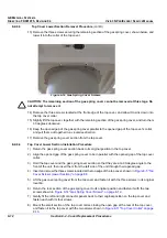
9) Plug in the AC cable to the AC Dis. Box, shown in
Figure 8-10 "AC Distribution Box Cables" on page
8-10
, and secure the cable to the other cables with a tie-wrap.
10) Plug all peripheral cables into their original locations in the connector panels.
11) Return the connectors panels cover, as described in
8-2-5-4 "Connector Panels Cover Installation
Procedure" on page 8-8
.
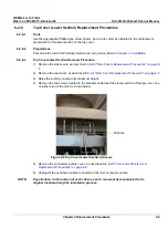
12) Fasten the top cover with the two screws located in the brackets underneath the top cover, on either
side of the unit, as shown in
Figure 8-9 "Top Cover (Lower Section) Screws" on page 8-9
.
13) Return the rear cover, as described in
8-2-4-4 "Rear Cover Installation Procedure" on page 8-7
.
14) Return the side covers, as described in
8-2-2-4 "Side Covers Installation Procedure" on page 8-4
.
8-2-7
Gas Spring Cover Replacement Procedure
8-2-7-1
Tools
Use the appropriate Phillips-type screw drivers, as indicated in the gas spring cover replacement
procedures.
8-2-7-2
Preparation
Shut down the Vivid 3N Pro/Expert ultrasound unit, as described in
Chapter 3 -
Installation
.
8-2-7-3
Gas Spring Cover Removal Procedure
The procedure for removing the gas spring cover is identical to the procedure for removing the lower
section of the top cover, as described in
8-2-6-3 "Top Cover Lower Section Removal Procedure" on
page 8-9
.
8-2-7-4
Gas Spring Cover Installation Procedure
The procedure for installing the gas spring cover is identical to the procedure for installing the lower section
of the top cover, as described in
8-2-6-4 "Top Cover Lower Section Installation Procedure" on page 8-12
.

