GE M
EDICAL
S
YSTEMS
D
IRECTION
FK091075, R
EVISION
04
V
IVID
3N P
RO
/E
XPERT
S
ERVICE
M
ANUAL
Chapter 8 Replacement Procedures
8-153
8-8-7
Sony UP-21MD Color Video Printer Installation - Procedure 2
NOTE:
This procedure (Installation Procedure 2) is for units that are not equipped with a previously-installed
B&W printer and VCR. It describes all steps required to install a color printer. The color printer is placed
on the top cover of the unit’s lower section and the additional shelf and belt supplied with the color
printer are not required.
1) Unlock the belt buckles located on the lower section of the unit’s top cover, and move the belt parts
to the sides.
2) Place the color printer on the lower section of the top cover.
3) Connect the cable’s BNC connectors R-G-B and SYNC to the color printer R-G-B and SYNC Input
connectors.
4) Plug the color printer remote cable to the color printer Remote 2 Input.
5) Plug the AC cable to the color printer AC IN socket.
6) Screw the Ground cable lug to the lower middle screw on the color printer’s rear panel.
7) Set the NTSC/PAL switch in accordance with your local color system.
8) Lock the belt buckles over the color printer, and tighten each belt by pulling the remaining length of
the belt to fasten the printer securely in position.
9) Reconnect the mains AC power cable from the wall outlet.
10) Turn ON the main circuit breaker located on rear of the Vivid 3N.
11) Turn ON the Vivid 3N by pressing the ON/OFF button on the Control Console.
12.)Select the activation key under System Configuration, VCR/ECG Tab, A/B Swap.
By default, Print B key will be B&W Video printer and Print A key will be Color Video printer. For
more information on switching printer settings, see
3-8-9 "VCR/ECG Tab" on page 3-44
.
8-8-8
Sony UP 21MD Color Video Printer Removal - Procedure 2
NOTE:
This procedure (Removal Procedure 2) is for units that are not equipped with a previously-installed
B&W printer and a VCR.
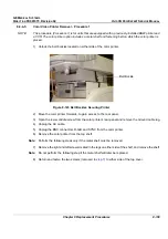
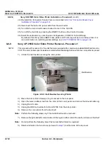
1) Unlock the belt buckles located on either side of the color printer, as shown in
Figure 8-140 "Belt
Buckles Securing Printer" on page 8-152
.
2) Move the color printer sideways to access its rear panel.
3) Open the lower middle screw on the color printer’s rear panel and remove the Ground cable lug.
4) Unplug the AC cable.
5) Unplug the cable's BNC connectors R-G-B and SYNC from the color printer RGB and SYNC Input
connectors.
6) Remove the color printer.

