GE M
EDICAL
S
YSTEMS
D
IRECTION
FK091075, R
EVISION
04
V
IVID
3N P
RO
/E
XPERT
S
ERVICE
M
ANUAL
8-20
Section 8-2 - Cover Replacement Procedures
8-2-11
Control Console Top Cover Replacement Procedure (Upper Section)
8-2-11-1
Tools
Use the appropriate Phillips-type screw drivers, as indicated in the replacement procedures for the
upper section of the control console’s top cover.
8-2-11-2
Preparation
Shut down the Vivid 3N Pro/Expert ultrasound unit, as described in
Chapter 3 -
Installation
.
8-2-11-3
Control Console Top Cover Removal Procedure (Upper Section)
1) Raise the control console to its
maximum
height.
2) Remove any peripherals.
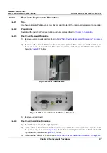
3) Unplug the AC cable and VGA cable from the rear of the control console, as shown in
Figure 8-18
"AC and VGA Cables at Rear of Control Console" on page 8-17
.
4) Remove the monitor, as described in
8-3-1 "Vivid 3N Monitor 15" Replacement - Procedure" on
page 8-28
.
5) Remove the two screws that fasten the rear section of the gas spring cover, and remove this
section.
6) Remove the three screws that fasten the front section of the gas spring cover, and allow this section
to sink down into the machine's top cover collar.
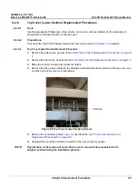
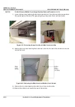
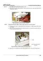
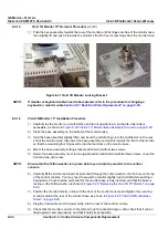
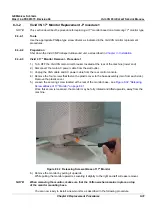
7) Remove the two fastening screws of the AC/VGA connectors box. These screws can be accessed
from the opened space at the rear of the gas spring using a long screw driver, as shown in
Figure 8-19 "Removing Screws from the AC/VGA Connectors Box" on page 8-18
. Move the AC/
VGA box away, to free it from the top cover.
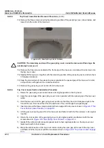
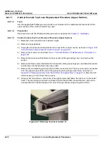
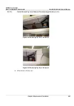
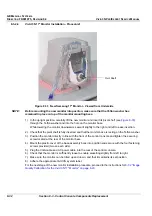
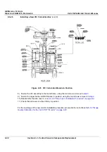
8) Using a short screw driver, remove six of the eight screws that fasten the top cover to the metal
frame. The remaining two screws are located next to the AC/VGA connectors box, and can be
accessed from the opened space at the rear of the gas spring using a long screw driver.
Figure 8-21 Removing Top Cover Screws (1)


